background image


2 - Display


  TASCAM MD-801R/P Mk II 


2–6


mode, the 


R E P E AT


 indicator will be shown on the dis-

play. See 4.2.9, "Repeat playback" for further details 
of this mode.


[27] INPUT LEVEL controls


These controls adjust the level of the signal at the 
analog connectors selected using the 


INPUT


 selec-

tion switch 


[28]


 (either the balanced inputs 


[36]


 or 

the unbalanced inputs 


[37]


) when the 


ANALOG 

INPUT


 switch 


[31]


 is set to 


UNCAL


When these controls are at about the “12 o’clock” 
position, they represent a nominal level for the unbal-
anced inputs (and for the balanced inputs if the trim-
mer potentiometers of the balanced inputs are still at 
the factory positions).

If the 


REC MODE


 switch 


[30]


 is set to the 


MONO


position, the 


L (MONO) INPUT


 control is used to 

control the level of the monaural signal.


NOTE


The level of signals received at the digital 


inputs 


[32]


 and 


[34]


 cannot be adjusted.


[28] INPUT selection switch


Use this switch to choose between the unbalanced 
analog inputs (


UNBAL


[37]


), the balanced analog 

inputs (


BAL


[36]


) or digital input (


DIGITAL


).


[29] DIGITAL INPUT switch


Use this switch to choose between the 


AES/EBU


digital input 


[32]


 and the 


COAXIAL


 digital input 


[34]


 when the 


INPUT


 selection switch 


[28]


 is set to 

the 


DIGITAL


 position.


[30] REC MODE switch


Use this switch to choose between monaural and ste-
reo recording. 

In monaural recording mode, the left and right sig-
nals are combined, and only the left 


INPUT


 level 

control 


[27]


 is used to control the level of the analog 

signals.

In monaural recording, twice the recording time is 
available on a disc than when recording in stereo.


[31] ANALOG INPUT switch


When an analog input has been selected using the 


INPUT


 selection switch 


[28]


, you can use this 

switch to bypass the 


INPUT


 level controls 


[27]


.

When this switch is in the 


CAL


 position, these con-

trols are bypassed, and have no effect. Signals are 

neither boosted nor attenuated, and a nominal signal 
will be received at the standard level of 4 dBu 
(balanced, 


[36]


) or –10 dBV (unbalanced, 


[37]


).

A signal at the nominal analog level (0 dB) will show 
as a reading of –16 dB on the unit’s meters (put 
another way, there is 16 dB of headroom available on 
the MD-801 relative to the nominal 0dB point).


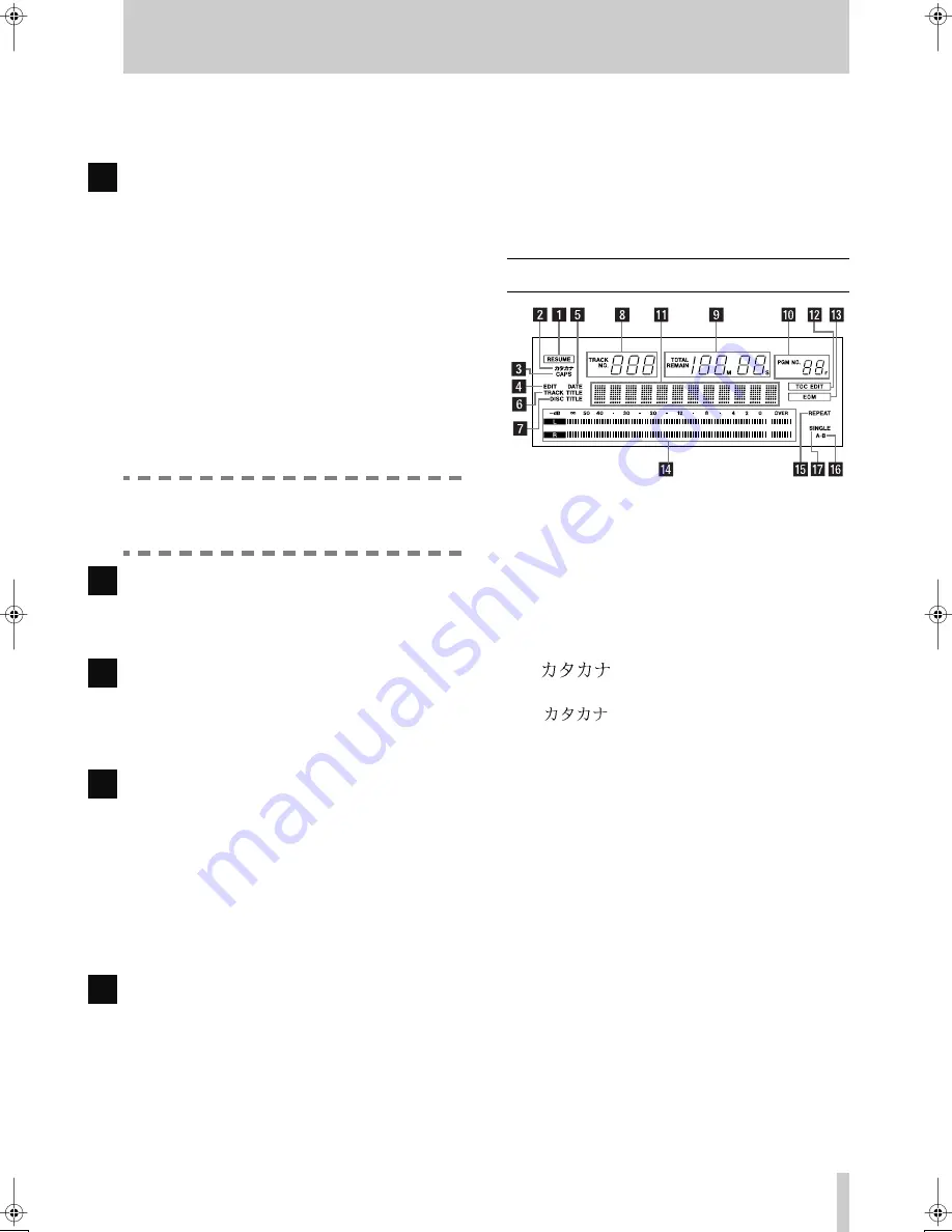
2.2 Display


The different indicators and parts of the display are 
shown here. We refer to the parts of the display 
which light and show preset messages as “preset 
indicators” or simply “indicators”.


(1) RESUME indicator


Lights when the resume mode is enabled from a 
menu (see 3.6, "Resume setting").


(2)

  indicator


Lights when the entry of Japanese 


katakana


 charac-

ters (

  is the word “katakana” written in 


katakana


 characters) is enabled, and will light if the 


TITLE


 key 


[16]


 is pressed when the 


MEMO IN/

CAPS 


indicator 


[23]


 is lit. Press the 


TITLE


 key once 

more to turn this off, and return to the entry of alpha-
numeric characters.


(3) CAPS indicator


Lights when capital (uppercase) letters are being 
used for title entry and editing (see 


[23]


).


(4) EDIT indicator


Lights when the unit is in EDIT mode. See 5, "Edit-
ing operations" for details of editing operations.


(5) DATE indicator


Lights when the unit is displaying the date on which 
a recording was made (the MD-801R records the 
date automatically). See 4.2.18, "Setting the time and 
date" for details of facility.

R

R

R

R

R

Summary of Contents for MD-801P Mk II

Page 1: ...terature accompanying the appliance The lightning flash with arrowhead symbol within an equilateral triangle is intended to alert the user to the presence of uninsulated dangerous voltage within the p...

Page 2: ...fit the fuse cover IF IN DOUBT CONSULT A COMPETENT ELECTRICIAN TO THE USER This equipment has been tested and found to comply with the limits for a Class A digital device pursuant to Part 15 of the F...

Page 3: ...rting structure grounding of the lead in wire to an antenna discharge unit size of grounding conductors location of antenna discharge unit con nection to grounding electrodes and requirements for the...

Page 4: ...2 DETTE M RKAT ER SOM VIST P ILLUSTRATIONEN ANBRAGT P INDERSIDEN AF TOPD KSLET FOR AT ADVARE BRUGEREN OM AT YDERLIGERE FREMTR NGEN VIL V RE FORBUNDET MED FARE FOR AT UDS TTE SIG FOR LASERSTR LING ADVA...

Page 5: ...2 5 5 DATE indicator 2 5 6 TRACK TITLE indicator 2 5 7 DISC TITLE indicator 2 6 8 TRACK NO display and indicator 2 6 9 Time display and indicators 2 6 10 PGM NO 2 6 11 Dot matrix alphanumeric display...

Page 6: ...Erasing a track 5 2 5 4 Combining tracks 5 2 5 5 Moving tracks 5 3 5 6 A and B point erase operations 5 3 5 6 1 Normal A B erase 5 4 5 6 2 Erasing to the end of a track 5 4 5 6 3 Erasing from the star...

Page 7: ...of the MD together with an area reserved for user recording Full explanations of the principles of magneto opti cal recording may be found in a number of excellent reference works but briefly during t...

Page 8: ...he shutter and touch the surface of the disc Do not keep MiniDiscs in excessively dusty loca tions in direct sunlight in areas subject to high temperatures or high levels of humidity If the cartridge...

Page 9: ...erial 1 3 1Unpacking the unit When you unpack the unit as well as the unit itself and this manual you should find Power cord Rack mount kit Warranty card If any items are missing contact your TASCAM d...

Page 10: ...kup time This indicates how long There are no features which are unique to the MD 801P model only When characters are shown on the unit s dot matrix display the following typeface is used Input Mon Al...

Page 11: ...1 Hookup Examplel TASCAM MD 801R P Mk II 1 5 1 5 Hookup Examplel...

Page 12: ...2 1 TASCAM MD 801R P Mk II 2 Front and rear panel features...

Page 13: ...TE key 4 TRACK keys These keys are used to move the playback position backwards or forwards a track at a time Their use is detailed in 4 2 Playback of discs 5 STOP key This key stops playback or recor...

Page 14: ...the value 13 SHUTTLE wheel This wheel can be used for shuttle playback for wards or backwards when the unit is in play or play ready mode Since the MD 801 is a digital audio device the sound output d...

Page 15: ...may be occasions where the two values shown do not always match exactly To turn off the time display in the lower part of the display press theTIME key until the disc or track title is shown rather t...

Page 16: ...d in the stop and the play ready modes Both the display preset indicators and the alphanu meric part of the display are used to show the current playback mode status as follows SINGLE SINGLE MODE Sing...

Page 17: ...e is available on a disc than when recording in stereo 31 ANALOG INPUT switch When an analog input has been selected using the INPUT selection switch 28 you can use this switch to bypass the INPUT lev...

Page 18: ...disc 13 EOM Lights briefly at the end of each track or at the end of the disc 14 Peak level meters Display the signal level on playback or when record ing MD 801R only NOTE The OVER indicator indicat...

Page 19: ...mmers are set to the standard 4 dBu level 37 ANALOG INPUTS UNBALANCED These RCA connectors accept unbalanced signals at the 10 dBV level The nominal impedance is 8 k 38 ANALOG OUTPUTS MONITOR These RC...

Page 20: ...onnector to attach either an optional RC 801 remote contoller or an optional RC FS10 20 remote controller Consult your TASCAM dealer for details of availability 47 REMOTE PARALLEL connector Use this c...

Page 21: ...nu has been opened with the SHUTTLE wheel the display changes See 4 2 13 Varispeed mode for details of pitch control operations 3 3 Auto cue The auto cue facility allows you to cue the playback positi...

Page 22: ...After the menu has been opened with the SHUTTLE wheel the display changes The time may be set from 1 to 99 seconds in 1 sec ond steps or set to off NOTE The EOM tally signal is always transmitted whe...

Page 23: ...ow the sub menus SHUTTLE wheel to open them 3 11 1Baud rate From the main menu the first sub menu allows the setting of the communications speed baud rate When this sub menu is opened the baud rate ca...

Page 24: ...value is 54 dB 3 14Copy ID When recording an MD on the MD 801 the copy ID of the recorded MD can be set for different purposes The three settings available are Copy Free Free allows unlimited digital...

Page 25: ...ing of the disc Stop playback with the STOP key 5 Pause playback with the READY key 7 and restart it with the PLAY key NOTE If the tracks being played back are less than three seconds in length playba...

Page 26: ...indicator goes out 4 2 6Playback between two location points 1 Enter the location points as described above 2 Press the PLAY MODE key 22 so that the display shows A B 3 Press LOC A DEL 24 The unit wi...

Page 27: ...taken place If repeat is active the unit will enter play ready mode at the start of the next track REPEAT continue the start of the track which is being repeated REPEAT SINGLE or the A repeat point RE...

Page 28: ...y mode press the MEMO IN CAPS key 23 so that the indicator is lit 2 Press theTITLE key 16 The word DATE will light in the display and the date will be shown for example 98y 12m 25d followed by the tim...

Page 29: ...ows Complete and theTOC WRITE indicator 19 lights press the TOC WRITE key to write the new TOC to disc NOTE Depending on the condition of the disc how many edits have been performed etc it may take a...

Page 30: ...the next TRACK key 4 Recording will continue but the track number is incremented by one and the track division is written at the point where the next TRACK key was pressed 4 3 5 Post Script recording...

Page 31: ...ying the source As soon as the signal level goes above the threshold the MD 801 will go from record ready to record mode If the MD 801 is in record mode it will drop back to record ready mode as soon...

Page 32: ...s is a special case when making copies between two MD 801 units Titles may be copied in either the analog or the digital copying modes A special optional cable PW 1XMD is required to link the two seri...

Page 33: ...ion to disc by press ing the TOC WRITE key 19 NOTE A disc must not be write protected when sav ing edits to disc The display shows W_Protected if you attempt to write a U TOC to a protected disc By ej...

Page 34: ...theTRACK keys or any other con venient way of locating to the track 2 After pressing the EDIT key turn the DATA dial until the display shows 3 Turn the SHUTTLE wheel clockwise to change the display 4...

Page 35: ...operty of the MD recording system 5 5 Moving tracks This function allows you to edit the running order of the tracks and re place a track in a different position This can also be used with the combine...

Page 36: ...the A point has been set it is erased the indicator goes out The B point will be at the position where the erase took place 5 6 1Normal A B erase In this editing operation both the A and B points are...

Page 37: ...int A If any of these conditions are not met the display will show A B Error 1 Mark the A and B points 2 Press the EDIT key and turn the DATA dial until the display shows 3 Turn the SHUTTLE wheel cloc...

Page 38: ...which this function does not restore such data and the Not Execute message will appear NOTES Tracks and sections of less than 12 seconds in length may not be restored When restoring a track or tracks...

Page 39: ...ach title can be up to 99 characters long and titles too long to fit on the display are scrolled The total number of characters which can be included as titles on a disc disc and track titles is 1 792...

Page 40: ...r following the position where a character is to be inserted 2 Press the LOC B INS key 24 A space will appear into which you can enter a character 5 11 3Changing characters If a character has been wro...

Page 41: ...aster MD 801 is in stop mode the DISC TITLE indicator will light in the display and you can copy the title for the whole disc If the master MD 801 is in play or play mode the TRACK TITLE indicator wil...

Page 42: ...pins 6 and 11 7 1 1Tally indicators The Tally pins of the REMOTE PARALLEL con nector may be used to connect LEDs etc for visual remote indication of the status of the functions which are associated wi...

Page 43: ...g this you should make sure that the value in the EOM track menu is set to off see 3 8 EOM track and that the EOM disc value is set to over 60 seconds see 3 7 EOM disc To connect two units for sequent...

Page 44: ...cording was not available Re check the connections etc to the MD 801 R R Disc Error The disc inserted is of the wrong type it may be an MD data disc or the U TOC has become damaged or is other wise un...

Page 45: ...tected The track has been pro tected and cannot be written Unprotect the track using the procedure described in 5 9 Changing track attributes TOC Edited Not an error message this message is shown when...

Page 46: ...acks nominal 10 dBV full scale 16 dB Maximum input level 6 dBV Nominal impedance 8 k AES EBU output XLR 3 32 type AES3 1992 format R R R COAXIAL output RCA pin jack IEC60958 consumer format SPDIF AES...

Page 47: ...8 Dimensional drawing 8 4 TASCAM MD 801R P Mk II 8 3 Dimensional drawing RC 8 Remote Control Unit RC 801 Remote Control Unit Option 216mm 200mm 58mm 1 5 6 m m 2 0 1 m m 1 4 m m 4mm 21mm 201mm 22mm...

Page 48: ...6 2 COAXIAL DIGITAL INPUT 2 8 DIGITAL OUTPUT 2 8 Combining tracks 5 2 Communications serial 3 3 Complete disc erasing 5 7 Compression ATRAC 1 1 Copy ID 3 4 Copying disc and track titles 5 9 title toge...

Page 49: ...acters 5 8 Introduction 1 1 J JOG key and indicator 2 3 Jog loop length 3 1 Jog mode 4 3 JOG DATA dial 2 3 Joop length jog 3 1 K Katakana indicator 2 6 Keyboard PS 2 track and disc title editing 6 3 u...

Page 50: ...connector 2 9 Remote control of the MD 801 7 1 REPEAT indicator 2 7 REPEAT key and indicator 2 5 Repeat playback 4 3 Replace recording 4 6 Restoring erased material 5 6 RESUME indicator 2 6 Resume set...

Page 51: ...and indicator 2 7 Track number incrementing 4 6 Track search operations 4 3 Track title copying together with audio 4 8 TRACK TITLE indicator 2 6 Track titles copying 5 9 Transport operations general...

Page 52: ...Centre Watford Herts WD1 8YA U K TEAC DEUTSCHLAND GmbH Phone 0611 71580 Bahnstrasse 12 65205 Wiesbaden Erbenheim Germany TEAC FRANCE S A Phone 01 42 37 01 02 17 Rue Alexis de Tocqueville CE 005 92182...

Reviews: