background image

50 

TASCAM  HS-8

MONITOR button: Monitoring mix (same signal output 

from the PHONES connector, which includes soloed 

signals, etc.)

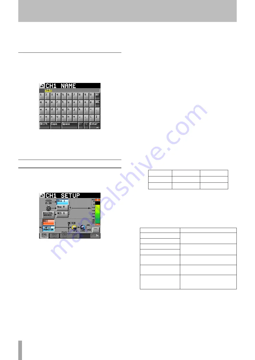
CHx NAME (button)

Edit the name of the channel (“x” is the channel).
Use the 

Shift

 and 

Caps

 buttons to change the available 

character types. 

Follow the same procedures to enter names as in “Editing 

the project name” on page 35, with the exception that 

there is no “Date” button. A maximum of 4 characters are 

allowed in channel names. 

Channel settings (CHANNEL SETUP)

Make settings for each channel. 
Select the channel using the tabs at the bottom of the 

screen. 

Ana x buttons (“x” indicates the channel number): Set 

analog input channel 1-8 as the input source.

Ana x buttons (“x” is “A” or “B”): Set analog input channel 

A/B as the input source.

AES x/ADAT x button (“x” indicates the channel number): 

Set AES/EBU digital input channel 1-8 or A/B or ADAT 

input channel 1-8 as the input source. 

DIGITAL SOURCE button: Touch this button to set digital 

input as the input source and open the “

CHx-x


DIGITAL


SOURCE

” screen where you can select the 

desired digital input connector. 

REC button: Arm or disarm recording. When armed, the 

button background becomes red. When recording, 

the signals of tracks that are enabled are recorded. 

Moreover, when a channel is armed for recording, 

the signal from the assigned input connector is input 

when the unit is stopped, recording or in recording 

standby.  (Default setting: disarmed—button not red) 

INPUT MONITOR button: Use to turn input monitoring 

ON/OFF. When ON for a channel, sound is always input 

through its input connector. 

Level knob: Touch the knob to adjust the level sent to the 

stereo bus. When its background color turns yellow, 

use the 

DATA

 dial to adjust it. Setting values range 

from –∞ to +10 dB. (Default setting: 0 dB)

Pan pot: Touch the knob to adjust the stereo position of 

the signal sent to the stereo bus. When its background 

color turns yellow, use the 

DATA

 dial to adjust it. 

Setting values range from L100 to R100 with C as the 

center value. (Default setting: C)

Level meter: The input signal level is shown for a channel 

when input monitoring is ON or recording is armed 

and it is not being played back. The playback level is 

shown during playback and for tracks that have input 

monitoring OFF.


The area beneath each level meter shows the track 

name (four characters or less) and indicates whether 

recording and input monitoring are enabled. 

Depending on whether or not recording and input 

monitoring are enabled, the background color will 

appear as follows.

REC Off

REC On

MON Off

Black

Red 

MON On

Blue

Red/blue


If the input source is set to a digital input and there 

is no signal on the corresponding digital input or 

the input signal differs from the unit setting, the 

channel meter display appears gray and the following 

messages appear. (The channels are indicated by 

x-x

”.)

Display

Description

AESx-x


NO


SIGNAL

If there is no input signal

ADAT NO SIGNAL

AESx-x


UNLOCK

If the input signal is not 

synchronized with the system

ADAT


UNLOCK

AESx-x


NOT AUDIO

If the Cbit information of the 

input signal is not audio

AESx-x NOT


PRO

If the Cbit information of the 

input signal is not professional

AESx-x


Cbit


ERROR

If other input signal Cbit 

information differs from the 

actual operation mode

Channel name button: Touch this button to edit the name 

of the channel.



 button: Touch this button to open the next channel 

setting screen.

6 – Internal Settings and Operations

Summary of Contents for HS-8

Page 1: ...HS 8 8 Channel Audio Recorder D01106920A OWNER S MANUAL...

Page 2: ...and found to comply with the limits for a Class A digital device pursuant to Part 15 of the FCC Rules These limits are designed to provide reasonable protection against harmful interference when the e...

Page 3: ...0 cm 4 in at the rear of the unit for ventilation 1 Read these instructions 2 Keep these instructions 3 Heed all warnings 4 Follow all instructions 5 Do not use this apparatus near water 6 Clean only...

Page 4: ...g operation limitations 29 Play a recording 29 Select a project folder take 29 Disabling input monitoring 30 Start playback 30 Mixing the playback sound 30 CALL 31 Flash start function 31 Online funct...

Page 5: ...k information 56 Erasing marks 56 Editing marks 56 Renumbering marks 57 Manual locate function 57 8 Operation using a computer keyboard 58 Setting the keyboard type 58 Use the keyboard to input the na...

Page 6: ...l Included items This product includes the following items Take care when opening the package not to damage the items Keep the package materials for transportation in the future Please contact the sto...

Page 7: ...n leave the unit for one or two hours before turning the unit on Cleaning the unit Wipe the unit with a soft dry cloth to clean it Do not use any benzine paint thinner alcohol or other chemical agents...

Page 8: ...the brightness of the color display 6 MENU key Press to open the MENU screen Press the MENU key while pressing and holding the HOME key to open the LOCK SETUP screen See Panel lock function on page 21...

Page 9: ...use a US keyboard To use a Japanese keyboard since the key allocation is different change the setting on the PREFERENCES page of the SYSTEM SETUP screen See PREFERENCES page on page 52 y PROJECT key P...

Page 10: ...e jog operation mode of the JOG SHUTTLE dial When this mode is enabled this indicator lights Press this key while pressing the SHIFT key to enable the shuttle operation mode of the JOG SHUTTLE dial Wh...

Page 11: ...RS 232C control Connect an external controller for example here NOTE This cannot be used at the same time as the RS 422 connector See RS 232C page on page 48 z PARALLEL connector This 25 pin D sub con...

Page 12: ...clock and video reference signal input You can input a word clock signal 44 1 kHz 48 kHz 48 kHz pull down 48 kHz pull up 88 2 kHz 96 kHz 176 4 kHz 192 kHz or a video reference signal NTSC PAL black b...

Page 13: ...e will perform the first listed function and can be used as conventional parallel controllers When this pin is low the above listed input pins will function as flash start keys Moreover the key assign...

Page 14: ...me elapsed from the beginning of the folder is shown The time remaining until the end of the folder is shown When recording the remaining amount of time that can be recorded on the currently selected...

Page 15: ...internal setting the channel meter display area appears grey and one of the following messages appears Display Description AESx x NO SIGNAL If there is no input signal ADAT NO SIGNAL AESx x UNLOCK If...

Page 16: ...ng operation limitations on page 29 Press this part of the screen to open the CF SELECT screen media selection screen See CF card selection on page 23 y REC MON button Touch this button to open the RE...

Page 17: ...er in the second half are different a take that has the same three digit number in the second half can be created When the unit is put in recording standby the file name of the next take to be recorde...

Page 18: ...18 TASCAM HS 8 2 Names and functions of parts a Manual Locate button Press this button to open the MANUAL LOCATE screen for locating manually See Manual locate function on page 57...

Page 19: ...rt the card Removing CF cards Turn the unit power OFF or stop operations before removing a CF card CAUTION Never remove a CF card during recording playback or anything else that accesses the CF card D...

Page 20: ...atch the display or cause malfunction The display touch panel is comprised of a film and glass Do not apply a strong force to its surface Doing so could break the glass When using the display do not p...

Page 21: ...the DATA dial on the front panel to change the value 5 Touch the SET button or push the DATA dial to confirm the setting NOTE After purchasing this unit set the clock before making your first recordi...

Page 22: ...34 minutes 16 bit 48 kHz 8 tracks stereo mix 2 hours 19 minutes 4 hours 38 minutes 9 hours 16 minutes 24 bit 44 1 kHz 8 tracks 2 hours 6 minutes 4 hours 12 minutes 8 hours 24 minutes 24 bit 44 1 kHz 8...

Page 23: ...NAGE screen 3 Touch the SELECT button next to the CF SELECT item to open the CF SELECT screen 4 Touch the button for the CF card that you want to use to select it The background of the selected CF car...

Page 24: ...n on the pop up message During formatting the following pop up message appears When formatting completes the following pop up message appears 5 Touch the OK button on the pop up message The CREATE PRO...

Page 25: ...w projects on page 34 3 After you complete making the settings touch the CREATE PROJECT button NOTE If a project with the same project name already exists the CREATE PROJECT button appears gray and yo...

Page 26: ...g the REC SETUP button Set the file format 1 Press the MENU key on the front panel to open the MENU screen 2 Touch the REC SETUP button to open the REC SETUP screen 3 Touch the FILE FORMAT tab to open...

Page 27: ...gs for each channel s input source For details see INPUT page on page 49 3 If necessary open the DIGITAL SOURCE SETUP and OUTPUT pages to make additional settings For details about the DIGITAL SOURCE...

Page 28: ...ding continues on a new file NOTE If you press the REC key less than 4 seconds after beginning recording the unit will not start recording a new take Depending on the Mono file recording folder settin...

Page 29: ...ing pop up message appears Moreover in these cases the remaining recording time indicator on the Home Screen shows Rec Limit NOTE The total number of items inside one folder includes files and folders...

Page 30: ...riefly to change the take While pressing the SHIFT key press the MARK and MARK keys to move between marks Press and hold the or keys to search backward or forward during playback While pressing the SH...

Page 31: ...reen that contains the takes you want to enable or flash playback NOTE The Flash Start screen contains five pages with 20 takes shown on each 5 Touch the FLASH LOAD button or press the DATA dial to lo...

Page 32: ...or folder is loaded The unit is put into recording standby or recording is started The CF card currently in use is removed Online function Turning this unit s Online Function ON allows switching to o...

Page 33: ...de files can be saved in one of two places folders SubFolder mode Subfolders are created for each take inside project folders and recorded audio files are saved in them Folder mode Recorded audio file...

Page 34: ...project MAKE FOLDER button Touch to open the screen where you can create a new folder MULTI SELECT button Touch to enable the selection of multiple folders MENU button Touch to open a pop up menu whe...

Page 35: ...project name already exists the CREATE PROJECT button appears gray and you will not be able to create a new project If this happens change the project name 4 Touch the OK button when the confirmation...

Page 36: ...screen NOTE When multiple projects are selected the EDIT NAME button in the pop up menu is not available 4 Input the project name using the procedures described above 5 Touch the Enter button on the...

Page 37: ...gress status pop up appears When rebuilding completes the pop up disappears NOTE If you rebuild when no project has been selected in the PROJECT screen the selected CF card is rebuilt entirely Erasing...

Page 38: ...to open the folder list 3 Select the folder that you want to load 4 Touch the MENU button to open a pop up menu 5 Touch the LOAD button in the pop up menu 6 Touch the OK button or press the DATA dial...

Page 39: ...r cannot be rebuilt 1 Press the PROJECT key on the front panel to open the PROJECT screen 2 Press the button for the project that contains the folder that you want to copy to open the folder list 3 Se...

Page 40: ...for the project that contains the take that you want to load 3 Press the button for the folder that contains the take that you want to load to open the take list 4 Select the take that you want to loa...

Page 41: ...tton on the PROJECT screen to show the pull up menu 6 Touch the EDIT TC button in the pull up menu to open the EDIT TAKE T C screen 7 On the EDIT TAKE T C screen and use the FRAME EDIT button to set w...

Page 42: ...42 TASCAM HS 8 TIP You can use this to mark the good takes for example NOTE You cannot edit take names 5 Projects...

Page 43: ...corded and disarm the tracks that are not to be recorded When a track is armed for recording the button background appears red Default setting no tracks armed buttons not red FILE FORMAT page Use this...

Page 44: ...of time allowing a maximum of 5 seconds before recording is started to be recorded To set the pre recording time touch the knob and adjust the value using the DATA dial The setting range is 1 5 second...

Page 45: ...emental play function ON or OFF When incremental play is ON press the PLAY key during playback to move to the beginning of the next take and continue playing or press the STOP RETAKE key during playba...

Page 46: ...tion of Project sampling frequency and Play sampling frequency settings the unit will operate with the Fs shown below Play sampling frequency setting Project sampling frequency OFF Default setting Pul...

Page 47: ...een SETUP page Make settings related to the time code generator STATUS This area shows the unit s current project time code frame type TC GEN MODE Set the time code generator mode FREE RUN The time co...

Page 48: ...functions This setting is synchronized with the Serial Mode item on the RS 422 page Baud Rate bps Set the transmission speed The options are 4800 9600 19200 and 38400 bps default setting Data Length S...

Page 49: ...ce for each pair of channels AES x x default setting 25 pin D sub AES EBU input AES A B XLR AES EBU input ADAT x x ADAT input Fs CONVERT buttons Turn the sampling rate converter ON or OFF for each pai...

Page 50: ...sent to the stereo bus When its background color turns yellow use the DATA dial to adjust it Setting values range from to 10 dB Default setting 0 dB Pan pot Touch the knob to adjust the stereo positi...

Page 51: ...digital input channel A B as the input source ADAT x x button x indicates the channel number Set ADAT digital input channel 1 8 as the input source Fs CONVERT button Turn the sampling rate converter O...

Page 52: ...yback to be used and always output the sound from all connectors For details see 9 Online functions on page 59 Ref Level Set the reference level for analog input and output to a number of decibels bel...

Page 53: ...v Scene002 T001_2 wav Scene002 T001_3 wav Scene002 T001_4 wav Scene002 T001_5 wav Scene002 T001_6 wav Scene002 T001_7 wav Scene002 T001_8 wav Scene002 T002 Scene002 T001_ST wav Scene002 T002_ST wav Sc...

Page 54: ...her management files and folders are created in addition to these File names The format used in naming files is as follows 1 8 track poly files Take name first half letter take number wav 1 8 track mo...

Page 55: ...ks Press the MARK or MAKR key while pressing and holding the SHIFT key to locate to the previous or next mark NOTE If MARK SKIP is input using parallel control the unit will locate to the next or prev...

Page 56: ...at are always created during recording Erasing marks 1 Select the mark that you want to erase on the MARK LIST screen or type of mark that you want to erase on the LISTINFO page MARK LIST screen LIST...

Page 57: ...Manual Locate button on the Home Screen to open the MANUAL LOCATE screen Touch the FRAME EDIT button to set whether or not the frame value can be edited FRAME EDIT ON FRAME EDIT OFF There are three l...

Page 58: ...o select the type of character to input Inputting characters You can use the number letter and symbol keys to import them directly Moving the cursor Use the keys Erasing characters Use the Delete key...

Page 59: ...8 AES EBU Digital output 1 8 ADAT Analog output L A R B Digital output L R Headphones RC HS20PD Headhones speaker If XLR Output Source is set to MONITOR the monitoring mix is output The signal output...

Page 60: ...on the front panel On the SYNC page of the SYNC T C screen set TC Chase to ON 3 If there is a take that can be synchronized with external timecode synchronized playback starts and the CHASE indicator...

Page 61: ...function and online playback mode settings Recording is not possible Reconfirm connections Adjust the recording levels If the CF card does not have enough capacity erase unneeded data and increase th...

Page 62: ...destination Do you want to overwrite that scene n 1 or 2 Cannot create more than 100 projects The maximum number of projects has already been reached so a new project cannot be created Cannot create...

Page 63: ...ot recommended n 1 or 2 CFn Read Error An error occurred when reading the card n 1 or 2 CFn unrecognized format Please Format this card This card has been formatted in a format other than FAT Format i...

Page 64: ...cannot be found Select a folder Load selected project pppppppp Confirm that you want to load the selected project pppppppp name of project to load Load selected Folder ssssssss Confirm that you want t...

Page 65: ...creen is not available while Recording The Project screen cannot be changed during recording Project Screen is not available in Jog Mode The Project screen cannot be changed when in jog mode Reading M...

Page 66: ...ed There is no project Please create a project There is no project so the recording cannot be made Please make a project There is no folder Please make a folder There is no folder so the recording can...

Page 67: ...ominal input level When reference level is 9 dB 6 dBu 1 55 Vrms When reference level is not 9 dB 4 dBu 1 23 Vrms Maximum input level selectable 15 dBu 4 36 Vrms 18 dBu 6 16 Vrms 20 dBu 7 75 Vrms 22 dB...

Page 68: ...ation of external synchronization 100 ppm Includes switch for enabling termination WORD VIDEO THRU OUT Connector BNC Output voltage 5V TTL equivalent Output impedance 75 10 Sampling frequency when usi...

Page 69: ...mm 465 7 mm 284 4 mm 14 4 mm 18 3 mm 76 2 mm 88 mm 94 mm Illustrations in this manual may differ in part from the actual product Specifications and the external appearance may be changed without noti...

Page 70: ...p Clip Record Tracks solo Volume solo Volume solo Volume solo Volume solo Volume solo Volume solo Volume Pan Pan Pan Pan Pan Pan Pan solo 2mix play limiter on Rec func Rec func Rec func Rec func Rec f...

Page 71: ...TASCAM HS 8 71 Notes...

Page 72: ...888 5939 Wallace Street Mississauga Ontario L4Z 1Z8 Canada TEAC MEXICO S A de C V www teacmexico net Phone 52 55 5010 6000 R o Churubusco 364 Colonia Del Carmen Delegaci n Coyoac n CP 04100 M xico DF...

Reviews: