


TASCAM DR-100MKIII
7
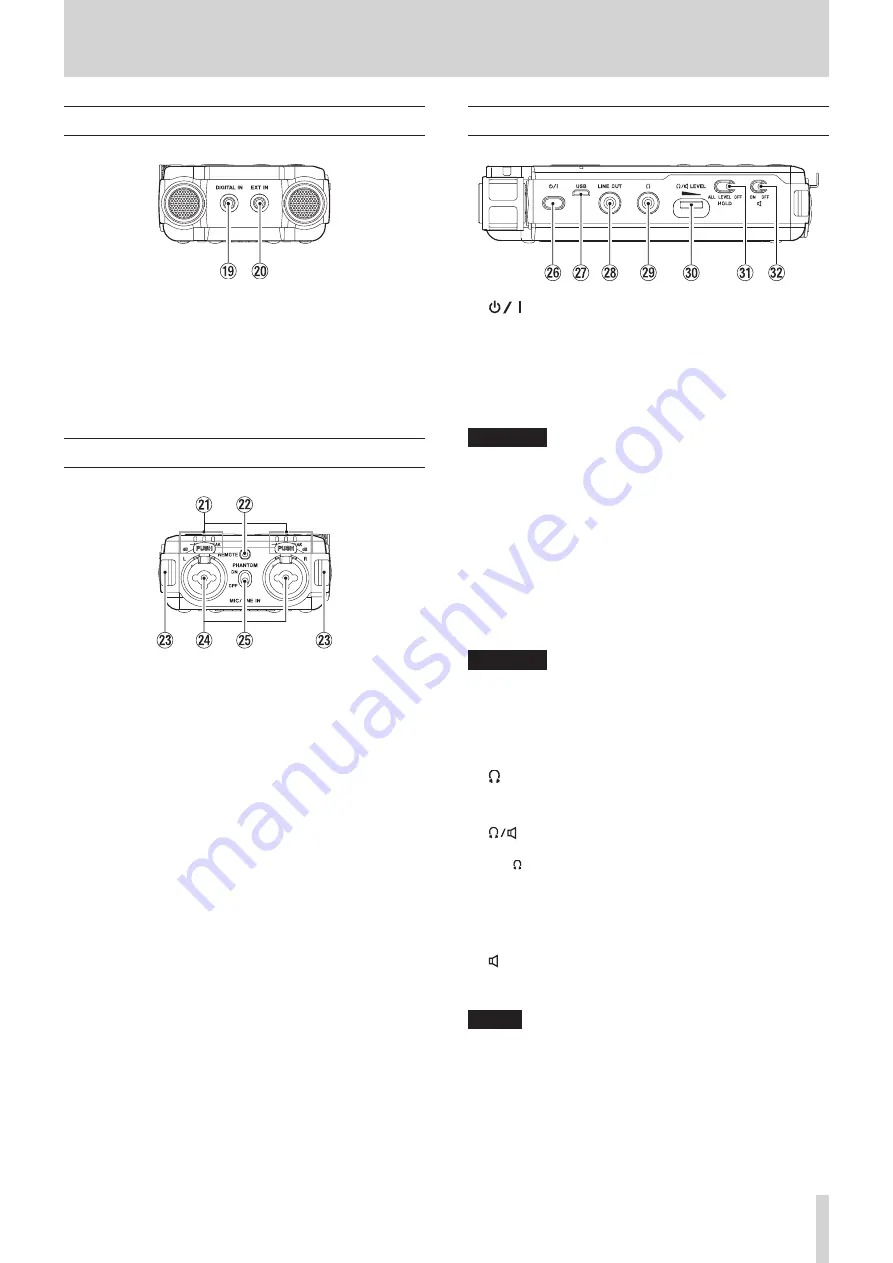
2 – Names and functions of parts
Front
o
DIGITAL IN connector
Connect the included digital input conversion cable to
input digital signals into this unit. (See “Recording from digital
p
EXT IN connector
Use a stereo mini jack cable to connect with the line output
jack of an audio device, for example.
Rear
a
Level indicators
The -48 (dB), -6 (dB) or PEAK indicators light according to
the input levels.
s
REMOTE jack
Connect a TASCAM RC-3F footswitch or TASCAM RC-10
wired remote control (both sold separately) here. This
enables remote starting and stopping of playback and other
functions. (See “9 – Connecting with a Computer” on page
d
Strap attachments
f
MIC/LINE IN L/R jacks (XLR/TRS)
These balanced analog jacks are XLR mic and standard TRS
inputs.
XLR (1: GND, 2: HOT, 3: COLD)
TRS (Tip: HOT, Ring: COLD, Sleeve: GND)
g
PHANTOM switch
Set whether phantom power is on or off for the MIC/LINE IN
jacks. (See “Using phantom power” on page 22.)
Left side
h
(power) button
Press and hold this button to turn the unit on and to put it
into standby (off).
Press and hold this button for at least 10 seconds while
pressing the STOP [
8
] button to force the unit to turn off
(enter standby).
CAUTION
Before turning the unit on, lower the volumes of connected
equipment to their minimum levels.
Failure to do so might cause sudden loud noises, which
could harm your hearing or result in other trouble.
j
USB port
This is a Micro-B USB port.
Use a USB cable (A to Micro-B) to connect the unit to a
computer. (See “9 – Connecting with a Computer” on page
45.)
The USB port can supply power to the unit. (See “Powering
CAUTION
The unit should be connected directly to the computer, not
through a USB hub.
k
LINE OUT jack
Use this to connect with the line input jack of an amp or
other equipment.
l
(headphone) jack
Use this jack to connect headphones. (See “Connecting
monitoring equipment” on page 19.)
;
(headphone/speaker) LEVEL volume
Use to adjust the volume output from the built-in speaker
and (headphones).
z
HOLD switch
Slide this switch to ALL or LEVEL to enable the hold
function that can prevent accidental operation. (See “HOLD
function for preventing accidental operation” on page 16.)
x
(speaker) switch
When set to ON, sound will be output from the built-in
speaker.
NOTE
Even when set to
ON
, sound will not be output when the
unit is recording, in recording standby or has headphones
connected.


