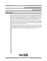
background image

1

Outputs

We also need to set up the outputs properly for our needs.  We need to make sure Direct 
outs 1-8 are going to TDIF 1, Direct outs 9-16 are going to TDIF 2 and Buss 1-8 is going 
to TDIF 3.  While we're here we'll also assign the Stereo buss to  Digital Out 1.

With the SHIFT key indicator lit, press the 
I/O key followed by soft key #3.  Use the 
cursor keys to highlight the first Output 
Signal field.  Use the data dial to scroll to 
BUSS 1-8/DIRECT 1-8 and press 
ENTER.  Use the same technic to change 
the next field to BUSS 1-8/DIRECT 9-16.
The next field should be BUSS 1-
8/DIRECT 1-8.  Set the fourth field to 
STEREO.

6

DM-24 Quick Start Guide
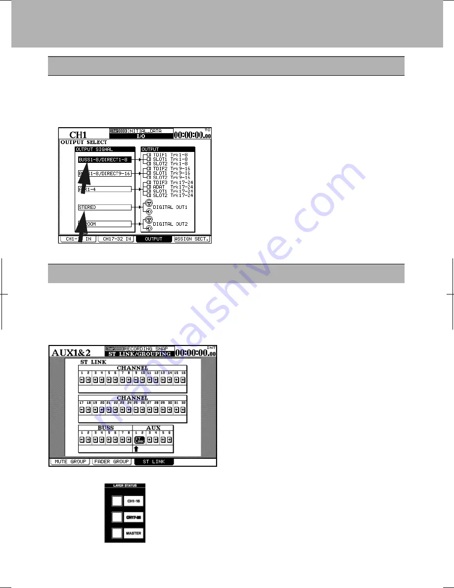
Tape returns

1


With the SHIFT indicator lit, press the 

     LINK/GRP key.  Press the soft key 
     under ST LINK.  Use the cursor keys
     to navigate the arrow under AUX 1 and 
     press ENTER.  AUX 1-2 will now show
     ST LINK.

2


Press the SHIFT key again so the indicator

     goes out.  Press the AUX 1-2 key.  Press
     the soft key below SOURCE.  Use the 
     cursor keys to highlight the SETUP 
     section of the display.  Turn the first
     POD knob to change setting to RETURN.
     Turn the second POD knob to change the
     setting to ALL.  Press ENTER.  A pop up
     screen will ask you to confirm by pressing
     ENTER again.  Do it.  You'll notice that the 
     first 16 channels are now labeled RETURN.

When recording on tracks 1-16 AUX 1-2 are used as the tape return path.  That being 
the case there are a few settings you will need to be aware of. This section will cover 
those settings. Tape returns for tracks 17-24 are different and will be discussed on 
another page.

Summary of Contents for DM-24

Page 1: ...Digital Mixing Console QUICK START GUIDE 9101441500...

Page 2: ...libration process may be inaccurate When the DM 24 is in operation do not cover the top surface and make sure that the heat sink at the rear of the unit is clear Always use recommended cables and conn...

Page 3: ...e the same equipment but this should help to serve as an example Connections to the DM 24 3 Assignable sends and returns are used to connect with external processors TDIF I O DA 45HR word sync input f...

Page 4: ...UT connector The DM 24 contains two high quality effect processors but in this example we are showing how to connect an external effects processor The DM 24 contains its own dynamic processors However...

Page 5: ...e appropriate M L mic line boxes with the channels as shown here If they do not they are linking the lower alternative source return to the channel Use the cursor keys to highlight the on screen patch...

Page 6: ...FT indicator lit press the LINK GRP key Press the soft key under ST LINK Use the cursor keys to navigate the arrow under AUX 1 and press ENTER AUX 1 2 will now show ST LINK 2 Press the SHIFT key again...

Page 7: ...he levels as you wish 3 Press the LAYER STATUS key for CH 1 16 and press the CH 1 SELECT key Turn SHIFT off and press the AUX 1 2 key Use the cursor keys to select Aux level fader control at the top l...

Page 8: ...the ASSIGN buttons Make sure CH 17 is NOT assigned to ST BUSS 1 8 or DIRECT OUT Make sure the same is true of CH 18 24 Bring faders 17 24 down Press the SHIFT key so the indicator goes out Now press t...

Page 9: ...s the MASTER LAYER STATUS key The faders will jump to show master buss and aux send levels Locate the AUX 3 and 4 master faders and bring them to a unity gain setting In other words push the faders to...

Page 10: ...r is lit and press the MONITOR key Use the cursor keys to highlight AUX 1 2 by the SEL 1 key Use the data dial to scroll through your choices Press the ENTER key to make a change Return to the CH 17 3...

Page 11: ...trol knob to browse your selection choices Choose ST stereo buss Press the soft key below ALL CH ON Notice that this assigns ALL channels to the stereo buss This is a quick way to see where all of you...

Page 12: ...ump straight to the EQ screen Choose one of the four EQUALIZER band selection keys to begin manipulating the frequency content of the program material on this channel 3 4 Use the graphical display at...

Page 13: ...w been changed to the appropriate settings for mix down Use the data dial to choose RECORDING and press the soft key under RECALL All of the DM 24 s parameters have now been changed to the appropriate...

Page 14: ...he screen move the cursor to the ADD button a t t he bottom of the list and press ENTER Move the cursor to the left side of the screen where the DA 78HR is listed Move the cursor to the TRA button and...

Page 15: ...channel EQ set to ON Hi 10 1kHz H SHELF Gain 0dB Hi Mid 5 04kHz Q 1 20 Gain 0dB Low Mid 1 26kHz Q 1 20 Gain 0dB Low 125Hz L SHELF Gain 0dB 2 All channel dynamics set to OFF 3 Compressor settings Thres...

Page 16: ...Module Return ST Link by Select Key Balance Level Center 0dB Select Key Follows Fader Level Fader Meter Follow Cursor Follows EQ Band Key Solo Mode Select Mix Solo Solo Link OFF Solo Type AFL NO Inpla...

Reviews: