


1
2
3
4
5
6
7
8
xvi
P r e f a c e
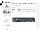
Fig. 1 5 Rear Panel (cover closed).................................................1-7
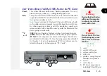
Fig. 1 6 Rear Panel (cover open) ...................................................1-7
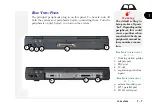
Fig. 1 7 Bottom Panel ..................................................................1-10
Fig. 2 1 Type Keys.........................................................................2-2
Fig. 2 2 Function Keys................................................................... 2-2
Fig. 2 3 PS/2 Keyboard Port ...........................................................2-3
Fig. 2 4 The TouchPad................................................................... 2-4
Fig. 2 5 The CD-ROM ................................................................... 2-6
Fig. 2 6 The LCD Controls ........................................................... 2-15
Fig. 2 7 Display Properties Control .............................................. 2-10
Fig. 2 8 Display Panel TV Settings .............................................. 2-11
Fig. 2 9 Audio Subsystem Ports ................................................... 2-13
Fig. 2 10 PC Card Sockets ............................................................. 2-15
Fig. 2 11 Fax/Modem Port ............................................................. 2-19
Fig. 3 1 Drive Modules .................................................................3-2
Fig. 3 2 Drive Indicator LEDs ........................................................3-2
Fig. 3 3 Removing the HDD ..........................................................3-4
Fig. 3 4 Assembling the HDD Cartridge ........................................3-5
Fig. 3 5 Module Removal ..............................................................3-7
Fig. 3 6 FDD Status Indicator ........................................................3-9
Fig. 3 7 Drive Bay with FDD ........................................................3-9
Fig. 3 8 FDD/Parallel Connection .................................................3-9
Fig. 3 9 Drive Bay with Zip (swappable with LS-120) ................. 3-11
Fig. 4 1 Sample Startup Screen: The POST ...................................4-2
Fig. 4 2 Setup Main Menu.............................................................4-5
list of figures