


16
17
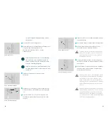
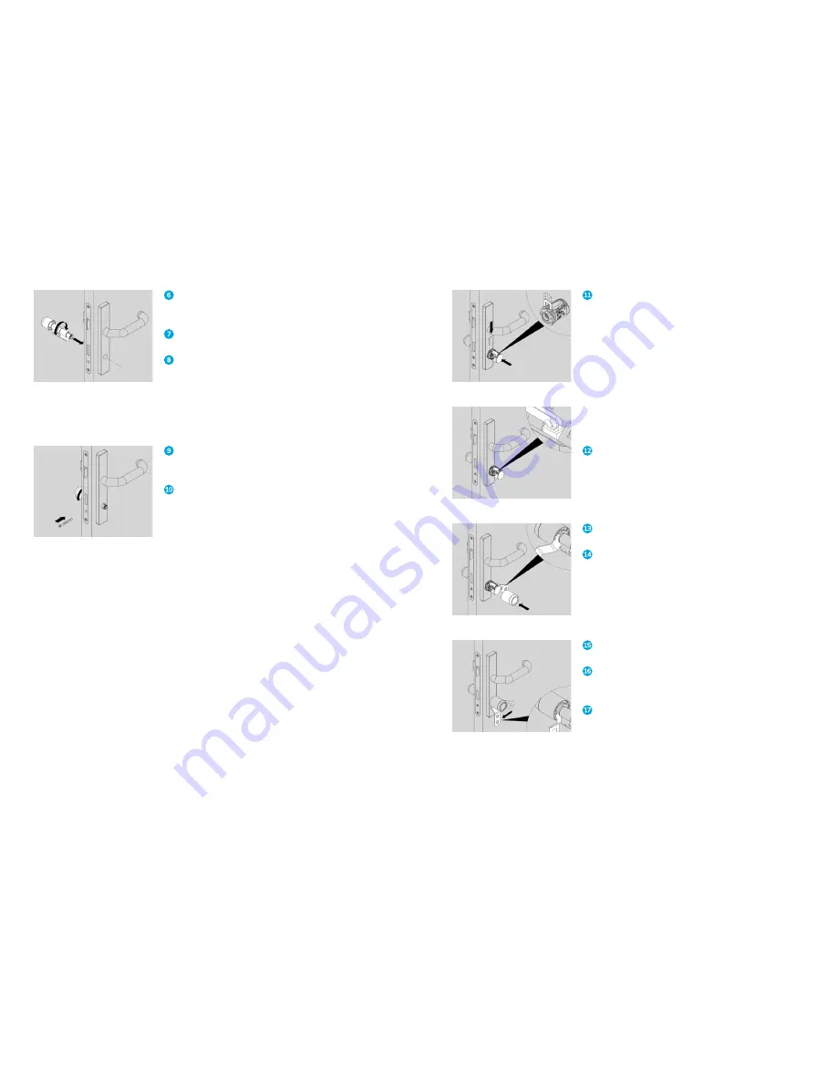
Remove the old locking cylinder if necessary
(not illustrated).
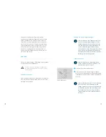
Align the cam flush with the cylinder body.
Carefully slide the cylinder through the fitting from
the inside with the outside forwards.
Caution: Do not tighten the screw with a cord-
less screwdriver without torque control, becau-
se you may damage the cylinder with the tool.
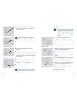
Turn the inside knob so that you can feel the
correct position of the cam and align the cylinder.
Fix the cylinder with the screw as soon as you feel
the correct position. Do not completely tighten the
screw yet.
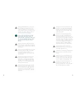
Caution: Avoid electrostatic charges prior to
the (dis)assembly of electronic components or
touch a conductive, grounded object (e.g. water
pipe, heating) beforehand to remove electrost-
atic charge from your body. Never touch the
electronics components with your fingers.
Caution: The battery cable must not be connec-
ted to the electronics holder when you push
the electronics holder in place. If the battery
connector should already be connected to the
electronics holder, always remove the battery
connector from the electronics holder first.
Fig. 9: Insert the cylinder
Fig. 10: Align cam
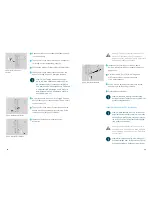
Slide the electronics holder accurately onto the
coupling shaft until it reaches the end position.
Secure the electronics with the fixing bracket.
Please note: The battery connector has a
torsion-resistant guide lug.
Insert the battery connector into the battery socket.
Place the knob tool on the bayonet fitting.
Slide the knob sleeve accurately over the electro-
nics holder. The knob sleeve can only be slid on in
one position. The two drive cams on the electronics
holder have different widths.
Lock the bayonet fitting using the knob tool.
Check that both knobs turn freely without
scraping on the fitting.
Tighten the screw.
Please note: Keep the original packaging
so that you can store the smart lock safely
at any time.
Fig. 11: Mount electronics holder
Fig. 12: Connect battery
Fig. 13: Slide on knob sleeve
Fig. 14: Locking the bayonet fitting