


8
Instruction manual CTM mag drive pumps
IOM manual Tapflo PE & PTFE series pumps
9
1.5
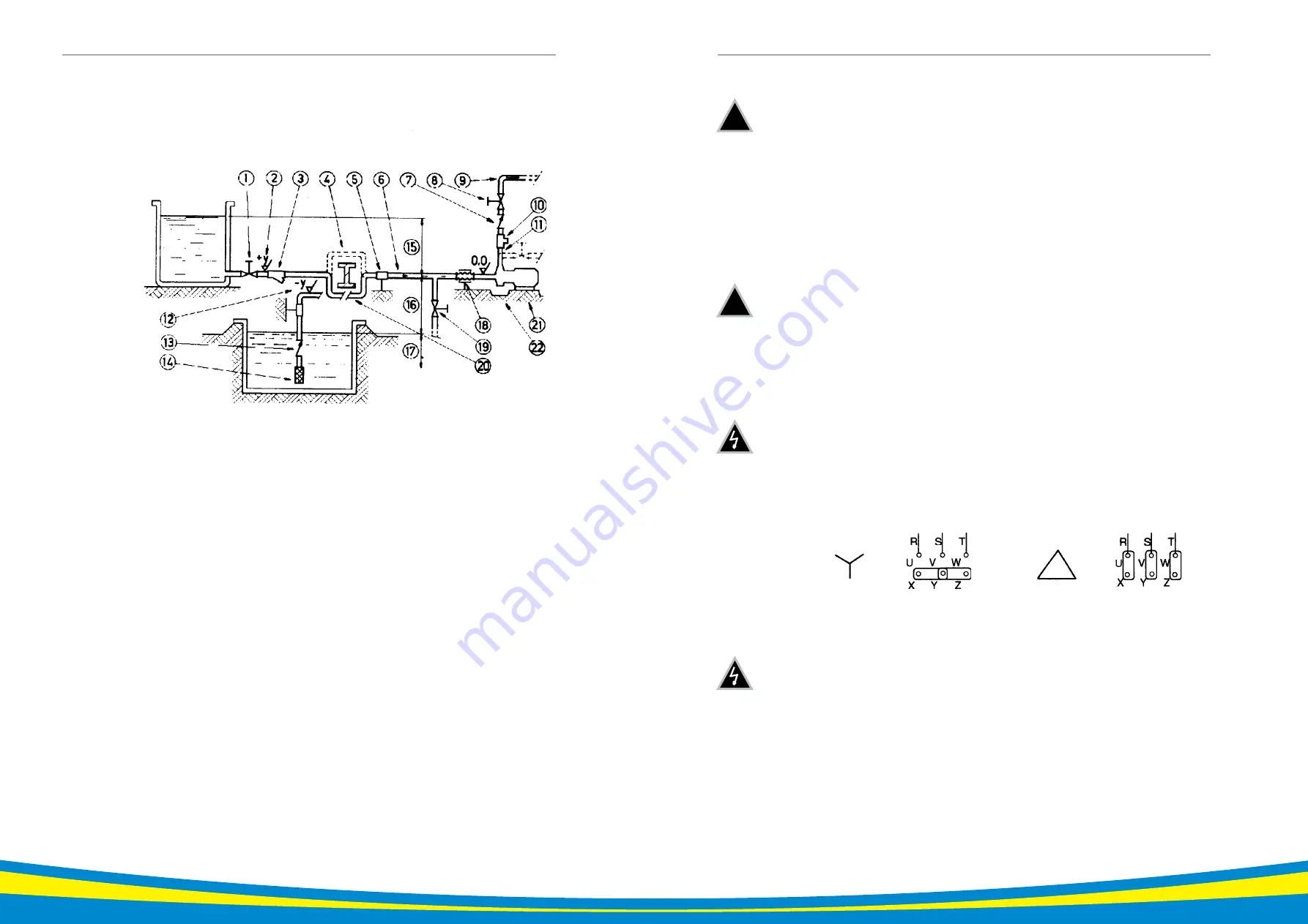
Example of installation
1) YES: gate valve (may also be near pump in the case of long piping)
2) With positive head: tilt of piping towards pump
3) YES: line strainer if particles are present
4) NO: air pockets: the circuit must be short and straight
5) YES: pipe fixing parts
6) Suction line as short and direct as possible
7) YES: check valve (especially for long vertical or horizontal pipes; compulsory with parallel
pumps)
8) YES: adjusting gate valve on outlet
9) Bends placed after valves and instruments
10) YES: attachment for gauge or safety pressure switch
11) NO: elbow joints (and other parts) on the pump (discharge and suction lines)
12) With negative suction lift: tilt of piping towards suction tank
13) YES: check valve (with negative suction lift)
14) YES: strainer if particles are present
15) Suction head varies according to flow in order to prevent windage
16) Suction head
17) Immersion depth
18) YES: expansion joint (indispensable with long pipes or hot liquids) and/or anti-vibration facility
during discharge and suction; anchored near to pump
19) YES: pipe discharge (completely sealed), discharge valve shut during normal operations
20) YES: overcoming obstacles at lower depths
21) Fix the pump by the fixing holes provided: the supports must be level
22) YES: drainage channel around base
1. INSTALLATION
1.6
Instruments
In order to ensure a reasonable control of the performance and the conditions of the pump installed, we
recommend using the following instruments:
- a pressure-vacuum gauge on the suction piping;
- a pressure-vacuum gauge on the delivery piping.
The pressure intakes must be made on straight pieces of piping at minimum five diameters from the
pump inlets. The pressure gauge on delivery must always be fitted between the pump and the shutoff/
regulation valve. The output can be read on the pressure, transformed into meters and then compared
with the typical curves.
Electric power
The electric power absorbed by the motor can be measured with wattmeters.
Optional instruments
The optional instruments can advise of abnormal operating conditions of pumps, such as: valves closed
accidentally, missing liquid, overloads, etc.
Thermometer
If the temperature of the pumped liquid can be a critical element, provide a thermometer (preferably
on suction).
1.7
Motor Connection
An expert electrician must always carry out the electrical connection. Compare the power supply with the
data plate specifications and then choose a suitable connection. The type of connection is stated on the
motor data plate that can be
Y
(star) or
D
(Delta), according to the power supply of the motor (see figure).
Star connection
Y
Delta connection
D
Follow the prescriptions of the local electricity board for the connection. In no case connect the electrical
motors directly to mains but also fit in between a suitable electric switchboard equipped with a knife
switch and suitable safety devices. Safety devices against overloads must protect the motors. Make sure
that the motor has suitable grounding and that it has been connected properly.
1. INSTALLATION
!
!