


b:
(Optional)
You may choose to allow the main speaker systems
to operate full bandwidth, in which case you will not require the
cables from the subwoofer outputs to the main speaker amplifier
inputs. This approach does not high pass your main speakers
and may or may not offer the best performance characteristics.
Some experimentation will be required to achieve optimum
results. (PS110 fig. 4, PS110B fig 5).
Ensure that your left and right channels have been connected
correctly through the chosen signal chain. Turn the gain control
to minimum. Turn the subwoofer amplifier "On" and verify the
LED is illuminated, indicating power is present. Note that the unit
features an auto on/off circuit, which will turn the subwoofer off if
there is no input signal for more than two minutes (indicated by
the green LED turning to red). The sub will instantaneously turn
on again, (indicated by the red LED turning green) as soon as an
input signal is received. Start your program material and adjust
your main speakers to the normal listening level. If you have high
passed the main speakers, do not be alarmed that they sound
thinner, all the energy below 80 Hz out of them for use by the sub-
woofer.
Now, adjust the subwoofer gain control until you’re satisfied with
a suitable level to match the main speakers. If something isn’t
working at this stage, you can go ahead to the troubleshooting
section, get things running, and then come back to find out how
to make it work even better.
5.0 Adjustable controls
a
:
Sub Level (Gain Control)
Adjusts the level of the subwoofer without affecting the signal
level that goes to your main speaker amplifier. Because the sub-
woofer has an integral crossover filter, this will also act as a bass
shelving control for your complete loudspeaker system. While it is
tempting to turn the subwoofer levels up, it is there to reproduce
low frequencies with less effort, and lower distortion, than the
main speakers alone can achieve. The most important thing is to
maintain a balanced audio spectrum.
b:
Crossover Frequency (Variable Low Pass Filter)
This adjusts the crossover point for the subwoofer. In this sys-
tem, that high pass filter point is fixed at 12 dB / Octave at 80 Hz.
The variable low pass filter has a range of 40 Hz to 150 Hz at a
24 dB / Octave slope, which allows you to adjust the amount of
overlap in the operating range of the subwoofer by about half an
octave. As you adjust the level of the subwoofer relative to the
main speakers, you will find that you need to adjust the low pass
filter point to avoid having a bump or hole in the bass response
at the 80 Hz crossover point. While you could think of this as a
bass control of sorts, it’s really there to help match the perform-
ance of your main speakers.
c:
Crossover Mode
Overrides the subwoofer internal low pass filter in the "all pass"
position. The "all pass" switch position can be used when experi-
menting with a discrete subwoofer channel arrangement. Careful
and thoughtful use of the controls are required to achieve the
best results.
For certain music and film production applications, it is mandato-
ry to run the L.F.E. (Low Frequency Effects) information through
an outboard proprietary production DSP unit. In this situation, it
is a requirement that the subwoofer being used has a linear fre-
quency response up to 300 Hz. This can be achieved by switch-
ing the crossover mode switch to the "all pass" position, which
overrides the subwoofers internal low pass filter. When no out-
board DSP processor is mandated, the internal low pass filter
must be engaged, (switch in the low pass mode) to operate the
internal low pass crossover frequency feature.
d:
LF Boost
This control offers the user the ability to boost the extreme low
frequency energy below 63 Hz, up to a maximum level of 4 dB in
a linear shelf mode. The maximum boost is obtained by turning
the adjustment knob fully clockwise. The boost is eliminated once
the knob is returned to the full counter-clockwise position. This
feature is to enhance extreme low frequencies for maximum
effects. As with all equalization, we advise its use in moderation.
e:
Phase Switch
Depending on the distance that your subwoofer is placed from your
main speakers, it may be necessary to reverse the phase of the
subwoofer. This is achieved by simply moving the switch to the
180 degree position. In most cases, you will find that the main
speakers will work best in the 0 degree position. In any case, trying
both positions of the switch will allow for quick reference. The switch
is in the correct position for your setup when the low frequency
output is greatest at, and below, the crossover point selected.
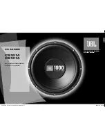
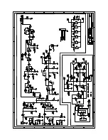
Right Speaker
Left Speaker
AMPLIFIER
A/V RECEIVER
OR
SURROUND PROCESSOR
Speaker Level IN
Speaker Level OUT
Left
Out
Left
Out
Right
Out
Right
Out
Right
In
Left
In
In
Out
Left
Right
Right
Left
-
+
+
-
PS110
Figure 2
Line level
setup for
PS110 suing
internal high
pass filter.
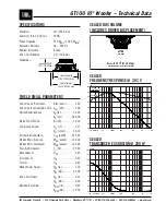
AMPLIFIER
Main
Speakers
Signal Source
PS110
Out
Out
Input
High Pass
Output
L
R
IN
IN
OUT
OUT
Figure 3
Line level setup for
PS110B using internal
high pass filter.
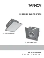
Sub Out
Speaker Level IN
Speaker Level OUT
A/V RECEIVER
OR
SURROUNG PROCESSOR
IN OUT
Left
Right
Left Right
+
-
-
+
PS110
Figure 4
Setup for discrete subwoofer
channel for PS110
Signal Source
Main Speaker
Amplifier
Main
Speakers
PS110
Out
Out
Out
Out
In
In
Out
Input
High Pass
Output
L
R
figure 5
Setup for
discrete
subwoofer
channel for
PS110B