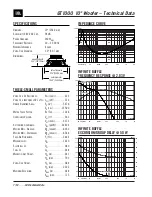


INPUT MODULE OPTIONS
PASSIVE (STANDARD)
The basic connection panel supplied with any of the 110 Series Subwoofers is a 8 Ohm speaker level input via barrier
strip. It is highly recommended that the audio signal be lo pass filtered via an outboard active crossover. This input module
is ideal for systems requiring several subs that share a common outboard crossover and amplifier.
PASSIVE 110 INPUT MODULE
SPKR LEVEL
INPUT
MADE IN CANADA
LO PASS FILTER
Speaker level inputs and outputs via barrier strip are passively filtered 100 Hz 12dB/octave LO pass for the subwoofer,
making this the ideal system for value and simplicity. The total impedance load of the satellite speaker(s) and subwoofer
should not be less than the minimum specified for your amplifier. Long wire runs to and from this module need to be an
appropriate gauge of speaker grade wire to retain proper damping and signal transfer characteristics.
LO-PASS
100Hz
PASSIVE 110 INPUT MODULE
SPKR LEVEL
INPUT
MADE IN CANADA
OUTPUT
PASSIVE 70 VOLT
(Passive 70 Volt available for either option of passive units)
A 70 Volt distribution amplifier is capable of supplying power to a number of remote speakers without concern of long
cable runs or varied impedance loads (limited to the amplifier power and line load).
The passive 70 Volt module takes
advantage of this type of installation with a 60 Watt transformer as the standard. A 150W 70V transformer version is
available upon request for both 70V passive options.
PASSIVE 110 INPUT MODULE
SPKR LEVEL
INPUT
MADE IN CANADA
OUTPUT
OUTPUT
LO PASS FILTER
NO LO PASS FILTER
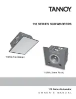
110
SUBWOOFER
70V 60W