background image

11 

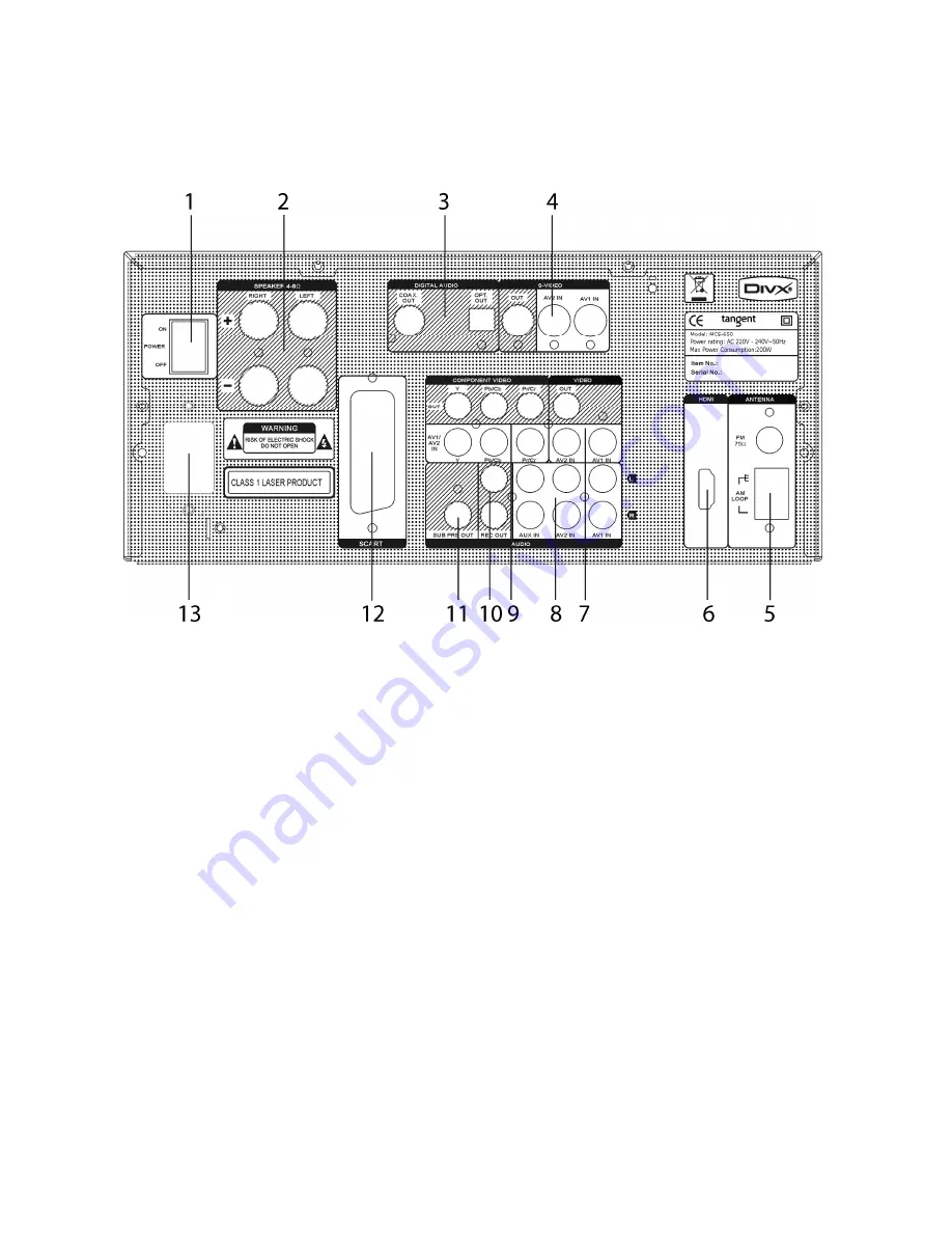
REAR PANEL CONNECTIONS AND BUTTONS 


The points below contains a brief description of the rear panel buttons, inputs and outputs. For more detailed 
descriptions of the functions and connections, please see the following pages of the manual. 


1. 

Mains power switch.  

Mains power ON/OFF switch. This is not a standby function. This is the mains power switch. When this 
switch is set to OFF, the receiver will not use any power at all. Please notice that the stored radio 

presets and sound adjustments will be erased from the receiver when it is turned off on the power switch 
for a period longer than one week. 

2. 

Speaker output terminals.  

For connecting the speakers of the system. Note that the impedance of the connected speaker must be 

between 4 and 8 ohm. Please make sure that the power is disconnected from the receiver while making 
any speaker connection. 

3. 

Optical and coaxial outputs.  

Optical and coaxial outputs for connection to a external sound processor, CD recorder, surround 

receiver, etc. 

4. 

S-Video output and inputs. 

S-Video output for connection to a TV set or monitor. 

S-Video inputs for the AV1 and AV2 inputs 

5. 

FM and AM antenna input.  

For connection of FM and AM antennas.  

FM antenna input.

 Connect the included FM antenna whip to this input or an external FM antenna. 

Make sure the cable used for this is a 75 ohms coaxial antenna cable. 

AM antenna input.

 Connect the included AM loop antenna to this input or an external AM antenna. 

Summary of Contents for MCS-650

Page 1: ...1 Instruction manual...

Page 2: ...an produce a product capable of achieving excellent performance and affordability www tangent audio com This operation manual supplies all the information that you need to have about your Tangent MCS...

Page 3: ...NECTION AF SPEAKERS 17 CONNECTION TO TV SET AND DIGITAL OUTPUTS 18 REAR PANEL INPUTS 20 FRONT PANEL INPUTS 21 THE SETUP MENU 22 Video Setup 22 TV Display 22 TV Type 22 Video Out 23 Angle Mark 23 OSD L...

Page 4: ...ed A symbol for CLASS II double insulation WARNING TO MINIMISE THE RISK OF FIRE OR ELECTRICAL SHOCK DO NOT EXPOSE THE UNIT TO RAIN OR MOISTURE DO NOT OPEN THE CABINET AS IT CONTAINS DANGEROUS VOLTAGE...

Page 5: ...hing or polarization If the plug cannot be inserted properly into the socket or if the plug does not fit the unit must not be used in your country Ventilation The cabinet is provided with slots and op...

Page 6: ...ry to persons or damage to the unit Damage Unplug the unit and contact qualified technicians in the following cases A If the power cord or the plug is damaged B If liquid has been spilled on the unit...

Page 7: ...it Touching the internal parts is dangerous and may cause injury or damage Do not open the cabinet Do not place any foreign matter in the unit Interference Placing the unit near a television set radio...

Page 8: ...e plug into a suitable socket Note If the unit is to be used abroad you may need an adapter CAUTION Do not turn on the power before all connections have been made correctly You might break your new un...

Page 9: ...ounterclockwise to adjust the master volume Turn the knob clockwise to increase the volume and counter clockwise to decrease the volume 4 USB input Use this input for connection of USB sources like a...

Page 10: ...ulti channel surround sound the sound in the headphones will be downmixed stereo When the headphones are connected the speaker outputs will turn off Make sure that the headphones you wish to use have...

Page 11: ...terminals For connecting the speakers of the system Note that the impedance of the connected speaker must be between 4 and 8 ohm Please make sure that the power is disconnected from the receiver whil...

Page 12: ...ts for the AV1 and AV2 inputs 10 Analog record output Analog output for an auxiliary stereo tape recorder or another source 11 Subwoofer output Pre output signal for connection of an active subwoofer...

Page 13: ...han 9 can be selected If the buttons are pressed for more than two seconds a station will be saved at the current number 3 Auto Enables and disables auto and manual search 4 Mem Use this button in com...

Page 14: ...d buttons to adjust 14 Treble Press this button to enter the treble adjustment menu Press the volume and buttons to adjust 15 Subtitle Press this button to change between the subtitles available on a...

Page 15: ...d exits the setup menu 35 Balance Press this button to enter the balance adjustment menu Press the volume an buttons to adjust Note It is possible to adjust the level of the subwoofer output here 36 V...

Page 16: ...e remote control Direct the remote control at the sensor on the front panel of the unit When the remote control signal is received the unit reacts accordingly The remote control works within a range o...

Page 17: ...aker with an impedance between 8 and 4 ohms The amplifier s colored speaker terminals are the positive terminals and the black terminals are the negative terminals The side of the speaker cable is mar...

Page 18: ...r Only picture no sound To use the component video output you must connect all three cables Y Cb Cr Y Pb Pr in the correct order To get component video picture to your TV set you must set the Video ou...

Page 19: ...sound through the HDMI can be set to either SPDIF or PCM depending on your TV set The audio output in the HDMI connection can be adjusted in the setup menu Please notice that not all TV sets features...

Page 20: ...S video input and a component video input Choose the AV1 or AV2 inputs by pressing the AV1 or AV2 TV button on the remote Please notice that if the AV2 TV button is pressed twice the sound and pictur...

Page 21: ...er or Memory stick to the unit to play music or see pictures You can browse the files of the connected source vi the TV set you have connected the MCS 650 through Please notice that the USB input on t...

Page 22: ...TV set It will cut the picture to make it fit your screen perfectly 4 3 Letterbox This setting will show 4 3 pictures on your screen normally and make a black bar in the top and bottom of the screen...

Page 23: ...GB Activates the RGB video output in the Scart connecter Note This setting is disabled when the HDMI output is activated Angle Mark Some DVD movies are recorded in multiple angles The Angle Mark featu...

Page 24: ...function will start a screen saver similar to the one known from a computer after approximately 60seconds You can choose between ON and OFF HDMI Resolution Here you can set the resolution of the HDMI...

Page 25: ...cter This feature is used if you are connecting the HDMI output of the MCS 650 to a surround receiver or surround processor Audio Setup The Audio setup enables you to make adjustments on the two digit...

Page 26: ...When this feature is active some audio track are not reproduced correctly Preference Setup In this menu you can make the most basic settings of the units DVD and DivX functions Audio This setting make...

Page 27: ...a DVD disc will be selected automatically if available Note This feature is not available on all DVD discs Disc Menu This setting makes you able to set a preferred disc menu language for playback of a...

Page 28: ...raph for further explanation to this The system is based on the rating information encoded on a DVD that classifies materials into 8 levels roughly corresponding to the Motion Picture Association of A...

Page 29: ...u must connect an antenna to the MCS 650 The receiver is able to receive both FM and AM radio It is therefore possible to connect both an AM and a FM antenna to the receiver 1 FM antenna input Connect...

Page 30: ...the TUNING button on the remote to step up or down in frequency If you press and hold the TUNING button on the remote the receiver will keep stepping up or down in frequency until you let go of the b...

Page 31: ...be only transmitted from the radio stations once a minute so you need to wait for less than 1 minute to see the time 2 NO CT will be shown if the signal from the radio station is not strong enough or...

Page 32: ...e is no significant damage on the disc The disc may be dirty clean it and re start again Does not play Make sure the disc is well installed with the label facing at the top The disc may be dirty and r...

Page 33: ...ope 9 kHz step Sensitivity 60 dB M Single to noise Ratio 50 dB Antenna Loop Antenna Video Section Inputs CVBS S Video and Component video Outputs HDMI CVBS S Video Component video and RGB Scart Level...

Page 34: ...34...

Page 35: ...35...

Page 36: ...36 Service hotline 45 9641 1599 For further information please visit our website Item No 40597...

Reviews: