background image

TANDBERG Videoconferencing System

43

General use

PC Presenter

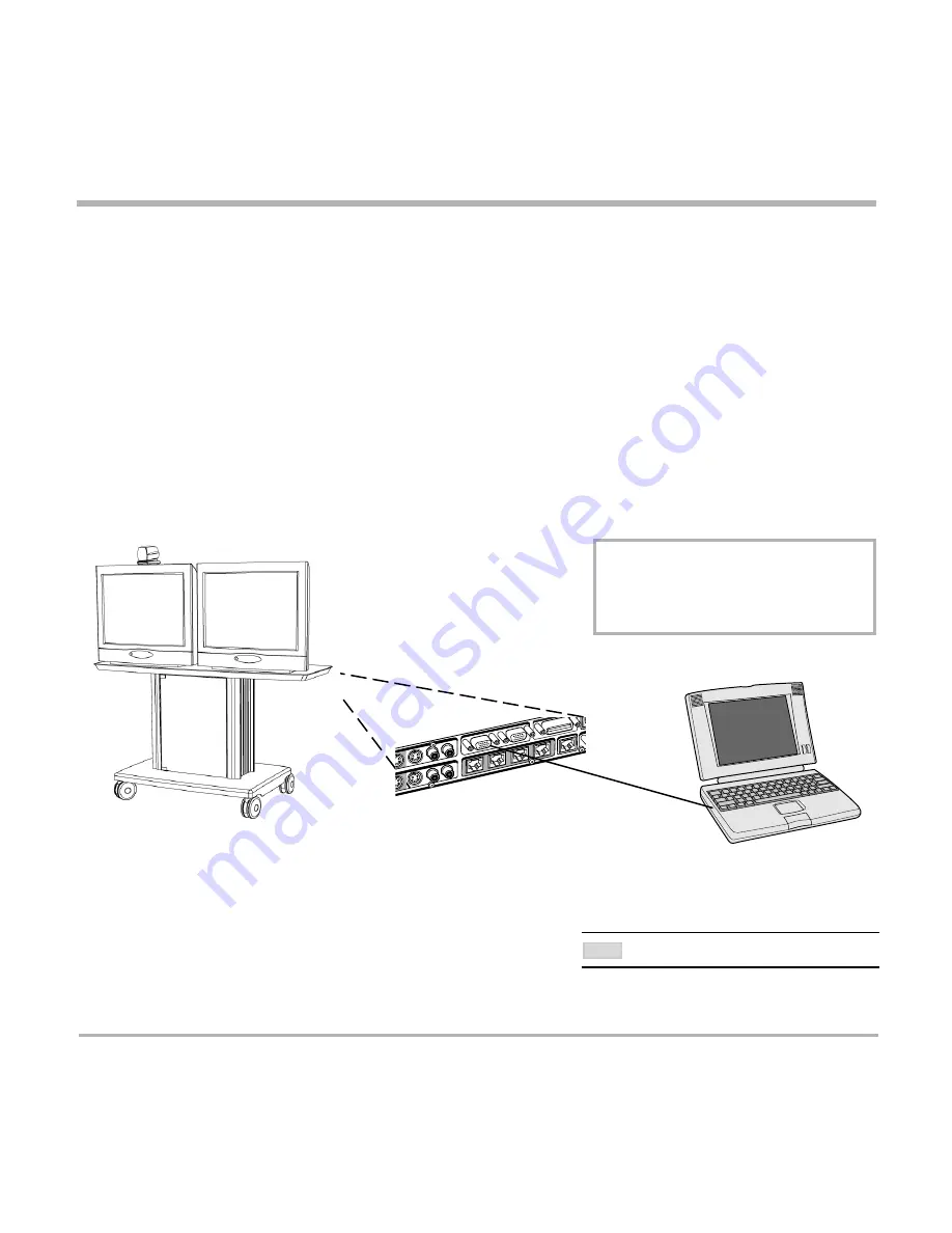
Plugging a PC into the system is made extremely simple through the PC Presenter, avoiding the need for any
additional hardware such as a projector, PC/Video converter or extra cables.

• Connect a VGA-VGA cable from your PC (VGA Output) to ‘VGA In’ on your system.

• Start your PC.

• Press 

PC

 on your remote control.

• Press 

S

ELFVIEW

 until the indicator ‘Selfview‘ is displayed on your main monitor (single monitor system) or until

you see the PC image on the second monitor.

If no PC image is displayed on your monitor, make sure that your PC transmits the image to the VGA Output, and
that the PC transmits a supported VGA-format (see tip below). Consult your PC-operating manual to see how to
transmit a VGA image from your PC (typically: Fn+F5).

PC Presenter input
(VGA In)

VGA Output

PC SoftPresenter *

PC SoftPresenter is used to display PC images on your system without using a VGA cable. The TANDBERG
video conferencing system and your PC must be connected to a LAN. In addition, VNC (Virtual Network
Computing) server software must be installed on the PC.

To show the PC image:
• Start the VNC software on your PC.
• Press 

PC

 on your remote control. Use UP/DOWN to activate PAGE UP/PAGE DOWN on the PC.

For setup information and details, see ‘VNC Settings’ in ‘Advanced use’.

PC: VNC

’ 

MUST


BE


SET


IN

 ‘

V

IDEO

 S

ETTINGS

’.

NOTE

* - Optional feature.

VGA-

FORMATS


SUPPORTED

 (VESA 

COMPLIANT

)

·VGA      640X480    60,72,75,85 H

Z

·SVGA    800X600    56,60,72,75,85 H

Z

·XGA      1024X768  60,70,75 H

Z

Summary of Contents for D12155-10

Page 1: ...1 Software version E3 B8 D12155 10 This document is not to be reproduced in whole or in part without permission in writing from UserManual...

Page 2: ...2 TANDBERG Videoconferencing System...

Page 3: ...or by any means electronically mechanically by photocopying or otherwise without the prior written permission of TANDBERG Nationally and internationally recognized trademarks and tradenames are the p...

Page 4: ...produce heat Grounding or Polarization Do not defeat the safety purpose of the polarized or grounding type plug A polarized plug has two blades with one wider than the other A grounding type plug has...

Page 5: ...0 Welcome menu 20 Basics 21 Making and ending calls 22 Directory 27 Microphone on off 30 General use 30 Adjusting volume 30 View outgoing video selfview 30 Do Not Disturb Sleep Mode 31 Selecting video...

Page 6: ...ork Configuration 69 LAN Settings 76 Call Settings 84 Dataport configuration 87 Language 89 Software Options 89 Diagnostics 90 Peripheral Equipment 94 Interfaces 94 Dual Monitor 96 Document camera 97...

Page 7: ...cipants at the far end to simultaneously watch a presenter on one screen and a live presentation on the adjoining screen Digital ClarityTF participants enjoy presentations of exceptionally high qualit...

Page 8: ...work Settings Inputs Outputs AGC Settings Restore Audio Defaults Level Settings Level Settings Line 3 Setup Exit Diagnostics Focus Brightness Whitebalance Video Name VGA Settings Disconnect Site Termi...

Page 9: ...TANDBERG Videoconferencing System 9 The TANDBERG 2500 Videoconferencing System At a glance the TANDBERG 2500 system...

Page 10: ...sitions using the remote control Monitor s The monitor displays the far end and near end videoconferencing sites in addition to the menus video from connected video sources and high resolution images...

Page 11: ...enu connect directory disconnect Cabinet The cabinet is easily movable with large wheels and handles The Codec is located inside the cabinet Below the Monitor s there is room for additional equipment...

Page 12: ...The ideal location for the microphone is on a flat surface at least 2m 6 5 ft from the front of the system The microphone cable should always point towards the system You can connect up to three micr...

Page 13: ...ations network This network type is only to be used behind a PABX X 21 network type is not approved for connection directly to the telecommunications network This network type is only to be used toget...

Page 14: ...onitor on top of the cabinet top plate and ensure it is stable You may fasten the monitor to the cabinet using the securing kit Take the camera and remove the plastic backing from the double sided tap...

Page 15: ...tion socket 2 Monitor cables Connect the S video cable to the input on your monitor see drawing For Scart monitors use the Scart adapter 3 Microphone cable Connect the microphone cable to the micropho...

Page 16: ...YOUR ISDN LINE SEE APPENDIX 1 5b Other networks using the External Network interface If you are using other networks please refer to External Network Settings and Appendix 2 6 LAN cable To use the sy...

Page 17: ...S NETWORK ISDN BRI SETTINGS SELECT THE RELEVANT LINE SETUP MENU AND SET ENABLED OFF Enter System Name to identify the system during an MCU conference Select Utilities System Name and enter the name us...

Page 18: ...d to be configured Press MENU on the remote control Select the menu Terminal Settings then Network Set Current Network to the network you want to use Specify the settings for the selected network in o...

Page 19: ...ol Select the menu Terminal Settings then LAN Settings Specify the necessary LAN settings according to the instructions from your LAN administrator If there is an H 323 Gatekeeper present on your LAN...

Page 20: ...elow After a few seconds you should see the Welcome menu on the monitor If this does not help verify that your monitor is switched on To switch the monitor on you normally push the power button on the...

Page 21: ...creen The text inside the blocks will change depending on which menu is selected The three Quick Keys have different colors Preset keys Activate pre stored camera positions Video source keys Activate...

Page 22: ...channels are dropped during a meeting Downspeeding automatically maintains the connection without interrupting the call in progress The SoftMux also enables you to dial to other videoconferencing equ...

Page 23: ...tar after the number and then enter the sub address extension address Example 12345678 10 number Sub address extension address MCU password When calling to external MCU s requiring a password TSC 1 th...

Page 24: ...l then be displayed NOTE TIP Choose the preferred quality by selecting the desired call rate in the Call Rate field You may also press the Set as Default Quick Key in order to make the selected bandwi...

Page 25: ...all subsequent calls If Auto is selected the system will select a network based upon the following criteria If an IP address e g 123 3 0 12 is entered LAN H 323 is selected If the first digits in the...

Page 26: ...nswer facility is switched off See Utilities in Advanced use End a call To end a call press DISCONNECT Correcting keying mistakes To delete the last digit or character entered press DELETE ENDING A CA...

Page 27: ...entries will not be displayed when you are in a call By using the dataport file system or external management systems like the TANDBERG Management Suite it is possible to store 400 additional entries...

Page 28: ...2x64 or 2x56 calls 3 Select Quality to specify call rate to be used 4 Select Set Restrict 56k to On to restrict the call rate A restricted call is a call to a 56Kbps network 5 Select Net to specify t...

Page 29: ...512KBPS TWO ENTRIES ARE ADDED ONE WITH 384KBPS AND ONE WITH 128KBPS 1 SINCE ALL SITES MUST USE THE SAME BANDWIDTH QUALITY PER SITE WILL BE 128KBPS 2 IN ADDITION MAXIMUM BANDWIDTH PER SITE CANNOT EXCEE...

Page 30: ...3 AND AUDIO4 IT WILL NOT MUTE AUDIO FROM THE AUX AND VCR INPUTS NOTE move pip General use Adjusting volume Press the VOLUME keys to adjust the volume level An on screen indicator will show the current...

Page 31: ...own On Screen Symbols The system has a number of symbols signalling different settings This symbol will be shown when the volume is turned off on the system This double padlock symbol will be shown wh...

Page 32: ...Settings in Advanced use When Sleep Mode is selected the following quick keys are displayed Pressing Sleep Now puts the monitors in sleep mode The system will still accept incoming calls Pressing 60 M...

Page 33: ...by pressing CamTrack On in the Preset 0 9 menu which is activated by pressing the P button on the remote control An on screen indicator CamTrackOn will appear When activating another video source e g...

Page 34: ...3 are the same presets as when pressing P and then a number key 1 3 Storing presets To store the current camera position audio and video source Press STORE once and wait for the on screen indicator to...

Page 35: ...control the far end camera use the keys below for pan tilt and for zooming Far end presets can be activated by pressing the keys P1 P2 P3 or the number keys 0 9 to activate presets P0 P9 Selection of...

Page 36: ...d on your screen Press SELFVIEW to return to normal view REQUIRES AUTO DISPLAY SNAPSHOT ON IN PRESENTATIONS Receiving a snapshot A received snapshot will automatically be displayed on your screen Pres...

Page 37: ...wing menu will be displayed Select video source to transmit on Duo Video Press CONNECT to add Duo Video AUTOMATIC DUO VIDEO HANDLES DUO VIDEO WITHIN THE SAME CALL IT IS NOT NECESSARY TO MAKE A NEW CAL...

Page 38: ...source in PIP and vice versa Pressing SELFVIEW will not change anything on the main monitor in a dual monitor setup Pressing MOVE PIP will move PIP only on the 2nd monitor in a dual monitor setup Cont...

Page 39: ...ished with the first site the other sites are connected one by one It is possible to either dial out to the sites or the sites can dial in to the MultiSite Optional feature SEE UTILITIES CONTINUOUS PR...

Page 40: ...tinuous Presence mode The cascaded systems connect to two other video sites plus one audio site each These systems will automatically run Voice Switched mode and transmit a full screen image to the ho...

Page 41: ...that you do not run out of bandwidth EXAMPLE IF THE SYSTEM HAS 512KBPS AVAILABLE AND YOU WANT TO CONNECT 3 SITES IN ADDITION TO THE HOST 128KBPS SHOULD BE SELECTED FOR THE FIRST CALL THE SYSTEM WILL T...

Page 42: ...mber 3 To dial in to the MultiSite on ISDN PRI Dial the main number of the system My ISDN Number All sites can dial the same number To dial in to the MultiSite on IP Dial the IP Number or the IP Addre...

Page 43: ...C transmits a supported VGA format see tip below Consult your PC operating manual to see how to transmit a VGA image from your PC typically Fn F5 PC Presenter input VGAIn VGAOutput PC SoftPresenter PC...

Page 44: ...LAN Settings in Advanced use for further information Start your Web browser In the address field type the IP address of the codec Enter the password and the Web page of the codec will be shown The de...

Page 45: ...l Procomm Plus and so forth The system has been specially designed to work with interactive programs and includes a data channel that can send and receive data to and from the far end at speeds of up...

Page 46: ...is possible to password protect the menus on the TANDBERG system To activate this feature specify a Menu Password in the Utilities menu By doing this only dialing and camera control commands will be...

Page 47: ...will not be transmitted This is useful if far end cannot handle these H 264 Auto Optimized video quality depending on what is available Off H 264 video compression and decompression will not be used c...

Page 48: ...ion and decompression H 263 Normal video compression and decompression H 261 Legacy video compression and decompression Off No video is transmitted Resolution Auto The setting of Video Auto Motion Sha...

Page 49: ...far end will not see the snapshot while you are adjusting it Duo Video Quality Auto Optimized video depending on selected video source and bandwidth in use Motion Duo Video is optimized for smooth mot...

Page 50: ...eo Snapshot Source Select which video source Duo Video transmits If you want the document camera to be the default source when using Duo Video snapshot select Duo Video Snapshot Source DocCam To use t...

Page 51: ...ff You must manually answer all incoming calls by pressing the CONNECT key Far end camera control On The far end will be able to Control your camera Select your video sources Activate your presets Req...

Page 52: ...video image of a different participant Off The active site will be displayed in full screen during a MultiSite conference Also called Voice Switched mode MCU status line On The MultiSite MCU DuoVideo...

Page 53: ...control the user will be asked to enter the Password written here Web Snapshots The system is able to generate JPEG snapshots and provide them to the world outside by request as http get or via ftp S...

Page 54: ...at the same time Chairman Control functionality enables one participant to control the meeting by selecting which of the conference participants is to be broadcasted to the other participants THIS SYS...

Page 55: ...will change to Release Floor If View Site is selected View Site will change to End View Selecting Take Chair will send a request to take chair If granted the Quick keys will be If Floor to Site is se...

Page 56: ...G THE DOC CAM OR PC VIDEO SOURCES Release floor You choose Release Floor to take you Off Air You should do this when you wish to make the floor available to the other participants in the conference Te...

Page 57: ...ase chair Allows you to release the privileges of chairmanship of the conference Floor to site Allows the chairman to select which of the conference participants is to be broadcast to all other partic...

Page 58: ...d 2 are intended for electret type microphones The microphone inputs are balanced with 24V phantom power Audio input 3 is intended for connection to external playback devices or to telephone add on hy...

Page 59: ...levels according to which external audio equipment is connected The on screen audio level indicator will make it easier to set the correct input level settings The input level should be adjusted so th...

Page 60: ...ED IN THE SAME ROOM AS THE MICROPHONES CONNECTED TO THE SYSTEM DOING THIS WILL CAUSE HOWLING AND POSSIBLE DAMAGE TO THE SPEAKER SYSTEM If an output is Off no audio will be sent to that output Level Se...

Page 61: ...are very significant the echo canceller may take a second or two to re adjust You can choose to switch off the echo canceller for the available audio sources ECHO CONTROL SHOULD BE SWITCHED OFF IF EX...

Page 62: ...ed Carpets curtains etc might require lower settings Adjust the setting NOTE on the far end if one of the following symptoms occur There is still some echo of your own audio Increase the setting The s...

Page 63: ...well as the signal Therefore in noisy environments it is advisable to turn the AGC off Tips for improving the echo canceller performance Place all microphones as far as possible from the loudspeaker...

Page 64: ...le to return all audio settings to their factory default settings by using Restore Audio Defaults The echo canceller tries to estimate the echo path from the speaker system to the microphones Moving o...

Page 65: ...an configure the system to activate an S video input when pressing doc cam on the remote control Video2 Video Input 2 S video will be activated when pressing doc cam on the remote control Video3 Video...

Page 66: ...ys to adjust Whitebalance In Auto mode the whitebalance is continuously updated To update the whitebalance manually select Manual and press OK A WHITE OBJECT SHOULD BE HELD IN FRONT OF THE CAMERA A FE...

Page 67: ...ain monitor VGA Out Quality VGA Out Quality changes the resolution of the VGA signal available on the VGA Out connector at the rear of the codec IF YOU SET VGA OUT TO MAIN MAKE SURE YOU HAVE A VGA MON...

Page 68: ...ivate VNC press PC on the remote control Please make sure that PC is set to VNC in the Video Settings Menu See also PC SoftPresenter section for further information VNC Settings VNC SERVER SOFTWARE SE...

Page 69: ...ify which network to use and define its settings If you want to use your system via ISDN BRI you should select Current Network ISDN BRI and enter the ISDN BRI Settings menu to set the BRI parameters I...

Page 70: ...LE UNUSED LINES ISDN switch type Select the type of ISDN network connected to your unit SOME SOFTWARE VERSIONS DO NOT SUPPORT 3 ISDN LINES THEREFORE SOME OF THE LINE SETUP ENTRIES MAY BE GRAYED OUT IF...

Page 71: ...SDN lines are not to be used set Enabled Off Line 1 should always be enabled National ISDN andAT T Custom ISDN might require SPID numbers associated with your ISDN numbers If you have received two dif...

Page 72: ...ht ISDN terminals to the same ISDN telephone number and line The terminals are addressed by using different subaddresses To call a terminal with a subaddress separate the ISDN telephone number and the...

Page 73: ...allel when setting up a BONDING call Off Channels will be dialed one by one which may increase the dialing time Send Own Numbers On The system will send its own numbers to the far end Off The system w...

Page 74: ...ing RS449 V35 Compatible when the external equipment uses RS366 ports Leased Line is a non dialing protocol and should be used when two codecs are connected in a point to point connection Use Leased L...

Page 75: ...h transmit and receive Cable Specification V 35 V 35 RS 366 cable Signal Name Female Male 34pin Male 25pin Comments 26pin DSUB Winchester DSUB Pin number Pin number Frame ground 1 A Signal ground 19 2...

Page 76: ...lient to know which stream to receive If the first codec streams on port 2240 and the second codec on port 2250 the client has to specify which port to listen to Video is transmitted on the specified...

Page 77: ...session Used by Cisco IP TV Off No announcement packets will be transmitted Video Rate Defines the Video streaming rate from the system Range is 16kbps 320kbps In addition audio G 711 streaming rate i...

Page 78: ...ias is not set Use Gatekeeper Auto The codec will automatically try to register on any available gatekeeper If a gatekeeper responds to the request sent from the codec within 30 seconds this specific...

Page 79: ...eper and Gatekeeper IP is disabled Off The codec will not use Cisco CallManager CallManager IP The CallManager IP address specified here will be used if Use CallManager On H 323 Prefix When dialing a...

Page 80: ...encing system when the IP traffic goes through an NAT router When NAT is On the NAT Server Address will be shown in the startup menu My IP Address 10 0 2 1 NAT NATAddress This must be the external glo...

Page 81: ...from 0 to 63 for each type of packets IP Type of Service TOS Helps a router select a routing path when multiple paths are available Delay Tells the router to minimize the delay Throughput Tells the ro...

Page 82: ...nes the network address of the codec This address is only used in static mode In DHCP mode the assigned IP address can be found on the Welcome Menu IP subnet mask IP subnet mask defines the type of ne...

Page 83: ...Trap Host SNMP Simple Network Management Protocol is used for monitoring and configuring of different units in a network The codec s SNMP Agent responds to requests from SNMP Managers a PC program et...

Page 84: ...ystem will accept incoming telephone calls Off The system will not accept incoming telephone calls This is useful to prevent incoming calls from systems other than videoconferencing systems Fallback t...

Page 85: ...fter the call is connected an open padlock symbol will be displayed When encryption has been established a closed padlock symbol will be displayed Off The system will not send or receive encrypted dat...

Page 86: ...u can enter the name of a profile prefix and network selection This is useful if you have a fixed prefix for your service provider Network Profiles This menu defines the settings listed when pressing...

Page 87: ...he control interface provided by the Dataport supports a subset of the Hayes command set as well as a comprehensive set of system specific commands This mode maintains communication with the Dataport...

Page 88: ...Codec will automatically detect WAVE cameras If you are using a camera supporting the VISCA protocol select Mode VISCA The Dataport 2 settings will then be enabled If Mode Auto and no camera is connec...

Page 89: ...unctionality A restart of the system is required after entering a new option key If the option key is invalid the original key will be used Language The system supports 11 different languages for its...

Page 90: ...is available through the Channel Status window This window indicates the various stages each B channel goes through whilst establishing a connection Status BRI Comments Idle the channel is idle Callin...

Page 91: ...2 No route to specified transit network WAN 16 Normal clearing 17 User busy 18 No user responding 21 Call rejected 28 Invalid number format incomplete number 29 Facility rejected 31 Normal unspecified...

Page 92: ...S DEFAULT SETTING WILL NOT AFFECT YOUR CALL DIRECTORY INFORMATION NETWORK TYPE LINE SETUP NUMBERS OR YOUR SPID NUMBERS NOTE Call status Comprehensive information about the call is available through th...

Page 93: ...mplementation of loop functionality The local side will see its own video and hear its own audio if the far end supports loop If Far End Loop is set to RequestRemote while in a call and the call is su...

Page 94: ...ou will be able to build your own applications for use with the TANDBERG 2500 thereby better integrating the system into your business environment This chapter will explain how to connect peripheral e...

Page 95: ...onitors The outputs are always active The format of the output will be either PAL or NTSC depending on your country s standard video format 4 Audio Inputs 2 microphone inputs balanced 24V phantom powe...

Page 96: ...r On in Utilities menu Alternatively you can use a PC monitor as your second monitor Connect VGA Out on the system to your PC monitor Set VGA Out Dual in VGA Settings menu XGA monitor The TANDBERG 250...

Page 97: ...a to the DocCam input on the Codec Press DOC CAM on the remote control to select the document camera as the video source See also Presentations for easy access to still image transfer from document ca...

Page 98: ...ility and is useful in large group applications The system is able to control up to 4 WAVE cameras Optional WAVE cameras are supplied with the necessary cabling In addition a external power supply is...

Page 99: ...tive for further information Tracker The Tracker is a small infrared remote control device made to used to steer the system camera to any desired location within the room Typically several Trackers wo...

Page 100: ...speaker system The audio from the VCR and your microphone s will be mixed and sent to the far end When a person talks on either local or far end the VCR audio level will be reduced to make it easier t...

Page 101: ...phone and speaker system The telephone add on connectors are marked AUX on the system audio input 3 and audio output 2 Audio output 2 provides a mixed signal between local and far end Extra fixed came...

Page 102: ...uters Appropriate communication software should be used for example Microsoft NetMeeting Intel ProShare Premier Windows HyperTerminal Procomm Plus and so forth The system has been specially designed t...

Page 103: ...at a distance from your table microphones it is possible to connect additional microphones to your system You can connect up to three microphones to your system The connectors are marked Mic1 Mic2 an...

Page 104: ...BERG can provide NT adapters For convenience the NT1 adapters could be placed inside the cabinet If needed use the shorter ISDN cable RJ45 connectors delivered with the NT1 between the codec and the N...

Page 105: ...pter No configuration of the Telesync Adapter is necessary Configuration of the system Select network type to National ISDN LINE 1 SETUP NUMBER1 program with number from the first SW56 line NUMBER2 pr...

Page 106: ...t results Avoid harsh side lighting or strong light from above Strong sunlight from a window or skylight may put part or all of the subject matter in shadow or cause silhouetting If you still have pro...

Page 107: ...e possibility of somebody inadvertently walking into the camera s field of view when entering the room Other than the conference participants there should be no moving items in the sent image system G...

Page 108: ...to point duovideo jpg Snapshot of the encoded stream if transmitting DuoVideo the decoded stream if receiving DuoVideo Description of the different folders user a folder to be used for custom logos e...

Page 109: ...located LOGO MAX SIZE E2 704X480 B7 320X200 FILE FORMAT JPG IF THE FILE IS TOO LARGE NO LOGO WILL BE DISPLAYED Type ftp IP address of your local codec Go to the user folder type cd user Upload the lo...

Page 110: ...whatever code you want and have access to the system The access txt file is a plain text file with one line per access code as shown below 1234 1250 A1 B2 ABC To upload this file to the codec follow t...

Page 111: ...rrect password Services The different IP services on the TANDBERG codec FTP Telnet HTTP SNMP and H 323 can be disabled to prevent access to the system By using the commands below the services can be i...

Page 112: ...me for systems on either side of an encrypted conference If the Check Codes do not match this would indicate that the call has been exposed to a Man In The Middle attack When a TANDBERG codec with Mul...

Page 113: ...TANDBERG Videoconferencing System 113 Appendices Appendix 6 Declaration of Conformity...

Page 114: ...s 15 Continuous Presence 54 Control mode 87 Copyright 3 Correcting keying mistakes 26 D Data mode 87 Dataport configuration 87 Declaration of Conformity 110 113 DES 85 112 DHCP 82 Diagnostics 90 Dial...

Page 115: ...Symbols 31 P PAL 95 Parallel dial 73 Password 77 PC 65 102 PC applications 102 PC Presenter 43 PC SoftPresenter 43 102 Peripherals 94 Phantom power 58 Picture in Picture 30 PIP 30 Precautions 13 Prese...

Page 116: ...he current camera position 34 To use the dataport for PC applications 103 Tracker 99 Trademarks 3 U Unpacking 13 Using a SUB address 72 Utilities 51 V VCR Playback 100 VCR Recording 100 VGA Out 67 VGA...

Reviews: