


tams elektronik
!
LC modules
English
Parallel connection of LEDs
With a parallel connection each LED has to be connected via it´s own
series resistor to the output. The total current at the output results
from summing up the current of each single LED.
The current consumption of one LED depends on the value of the series
resistor. The higher the value, the lower is the current and the more
LEDs can be connected to one output. But, the LEDs light the darker,
the higher you choose the series resistor´s value.
Caution:
The maximum current of 100 mA per output should not
be exceeded. In this case the output would be damaged.
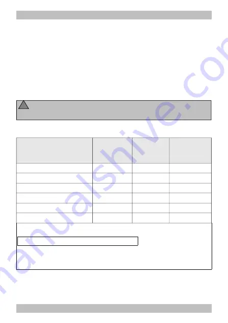
Examples for parallel connection of LEDs:
Power supply
Series
resistors
Current per
LED
max. number
of LEDs
per output
transformer (~) | 12 V
1,5 kOhm
10 mA
10
transformer (~) | 12 V
820 Ohm
20 mA
5
transformer (~) | 15-16 V 2,2 kOhm
10 mA
10
transformer (~) | 15-16 V 1 kOhm
20 mA
5
transformer (~) | 18 V
2,7 kOhm
10 mA
10
transformer (~) | 18 V
1,2 kOhm
20 mA
5
The calculation of the series resistors is based on the following formula:
series resistor [kOhm] = power supply [V] / current [mA]
Note: The operating voltage with a.c. transformers is approx. 1,4 times the nominal voltage
given on the transformer. With d.c. power packs the operating voltage corresponds to the
given nominal voltage.
Page 27


