www.tamcodampers.com
© T.A. Morrison & Co. Inc., 2020
INSTALLATION OF
DAMPER TYPES
&
2
VERIFY BEFORE INSTALLATION!
9
Before installing, inspect backdraft damper for possible damage
caused in shipping, and that it has not been racked or twisted.
Measure the damper from corner to corner to verify that it is square.
9
If minor damage has occurred to frame corners or flanges,
correct by bending or hammering back into position. Ensure
correct realignment of repair, as bent or twisted frames might
not mate properly with mounting angles, or additional backdraft
damper sections.
9
Do not install backdraft damper if damage is more than
superficial.
9
If uncertain as to extent of damage, or if damper does not oper-
ate correctly, call TAMCO Customer Service at 1-800-561-3449.
9
Compare items listed on packing list with materials received to
ensure all parts of the shipment are accounted for.
INSTALLED IN DUCT TYPE
>
Verify that backdraft damper is square.
>
Backdraft damper is manufactured so that finished O.D. is
¼”
(6.4 mm)
smaller than opening width and height dimensions.
>
Ensure that duct is square and/or large enough to allow backdraft
damper to be installed square.
>
Insert entire backdraft damper into opening. Bottom of damper
frame must sit flat on floor of duct to prevent twisting, sagging, or
bowing.
>
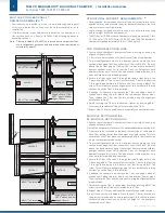
Install single-section units using mounting clips or angles. Arrange
clips (angles) snugly against the perimeters of the front and back
damper frames, securing clips (angles) to duct work.
(TAMCO
recommends that the clips (angles) should be fastened to the duct
work only, and not to the backdraft damper. This will prevent the
fasteners from binding or twisting the damper.)
>
If access to both sides of the backdraft damper is limited, install
clips (angles) to the duct work around the perimeter of either the
front or the back frames. Then secure the clips (angles) to the
damper frame.
>
TAMCO recommends that a minimum of two fasteners per frame
length be used (top, bottom, left and right). Fasteners should be
spaced at 12”
(305 mm)
to 15”
(381 mm)
oc.
>
Caulk all connections/joints between damper frame and duct to
minimize installation leakage.
FRONT OR REAR FLANGE INSTALL TYPES
>
Verify that backdraft damper is square.
>
Inserted portion of backdraft damper is approximately ¼” (6.4 mm)
smaller than specified duct size.
>
Ensure that the substrate the backdraft damper will be attached to
is flat and level.
>
Pre-drill fastener holes in the backdraft damper flange, before
placing over opening, to reduce twisting and binding.
>
Place single-section units directly on wall or floor. Secure backdraft
damper's flange to substrate using appropriate fasteners.
>
TAMCO recommends that a minimum of two fasteners per frame
length be used (top, bottom, left and right). Fasteners should be
spaced at 12” (305 mm) to 15” (381 mm) oc.
>
Do not overtighten fasteners to substrate. Doing so may damage or
twist the backdraft damper, which will increase air leakage.
>
Caulk all connections/joints between damper frame and duct to
minimize installation leakage.
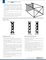
Front Flange
Rear Flange
Installed In Duct


