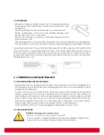
Ground mount
· Select the height of the mounting system to prevent the lowest edge of the module from being covered by snow
for a long time in winter in areas that experience heavy snowfalls.
· In addition, assure the lowest portion of the module is placed high enough so that it is not shaded by plants or
trees or damaged by sand and stones driven by wind.
Roof mount
· When installing a module on a roof or building, ensure that it is
securely fastened and cannot fall as a result of wind or snow loads.
· Provide adequate ventilation under a module for cooling; the
recommended standoff height is 10 cm. Clearance of 1/4 of an
inch (6.35 mm) or more between modules is required to allow for
thermal expansion of the frames.
· For roof mounting applications the assembly is to be mounted
over a fire resistant roof covering rated for the application. Talesun
modules have been listed as Class C according to UL790 standard.
· Any roof penetration required to mount the module must be properly sealed to prevent leaks.
· In some cases, a special support frame may be necessary.
· The roof installation of solar modules may affect the fireproofing of the building construction.
· Do not install modules on a roof or building during strong winds to prevent accidents.
· All module support structures used to support PV modules at correct tilt angles should
be wind and snow load rated by appropriate local and civil codes prior to installation.
Pole mount
· When installing a module on a pole, choose a pole and module mounting structure that will withstand anticipated
winds for the area.
Method A: Frame Holes Mounting
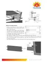
Modules must be securely attached to the mounting structure using
four pre-drilled mounting holes in the frame.
· Modules should be bolted to support structures through mounting
holes located in the frame’s back flanges only. Do not drill addi-
tional holes. Doing so will void the warranty.
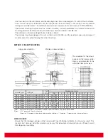
· Each module must be securely fastened at a minimum of 4 points.
If additional wind or snow loads are anticipated for this installation,
additional mounting points should be used. System designer and
installer are responsible for load calculations and for proper design of support structure.
· Use appropriate corrosion-proof fastening materials. All mounting hardware (bolt/spring washer/flat washer/nut)
should be stainless steel M8 size.
· Follow mounting guidelines recommended by the PV mounting supplier. The mounting design must be certified
by a registered professional engineer.
· The mounting design and procedures shall comply with local codes and all authorities having jurisdiction.
· Use a torque wrench for installation. Tightening torques should be within 10~17 Nm for M8 coarse thread bolts,
depending on bolt quality class.
Summary of Contents for TP672M-315
Page 16: ...www talesun eu com...


