background image

Function Descriptions

Rear Panel

1

2

3

3

4

5

1

2

3

4

5

6

① 

Antenna Connector B (ANT-B): used to connect an external antenna.

② 

Balanced Output Socket (BALANCED-B): XLR connector; signals of the two channels are output 


separately.

③ 6.3mm Unbalanced Output Socket (MIXED OUTPUT): signals of the two channels are mixed into 


one output.

④ 

Power Socket (DC INPUT): accept power supply to the receiver via a power adapter.

⑤ 

Balanced Output Socket (BALANCED-A): XLR connector; signals of the two channels are output 


separately.

⑥ 

Antenna Connector A (ANT-A): used to connect an external antenna. 

Receiver (Dual-Channel)
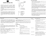
Front Panel

① 

Infrared (IR) Sync Window: transmit frequency parameters to the transmitter to sync transmitter 

     with receiver frequency, by using the “SET” button.

② 

LCD Display: display the system working status.

③ Up/Down Buttons (        ): used mainly for frequency and volume adjustment.

④ 

Confirmation Button (SET): press it to start or confirm menu selection.

⑤ 

Power Switch (POWER): used for power supply control of the device.

13

UC

-

2R

/

UC

-

4R


Wireless


Microphone

Summary of Contents for UC-2R

Page 1: ...UC 2R UC 4R Wireless Microphone...

Page 2: ......

Page 3: ...UC 2R UC 4R 400 6828 333 UC 2R UC 4R 01 CPU LCD XLR 6 3 1U OK UC 2R UC 4R N50dB XLR output jack 250mV 600Q 1 4 output jack 400mV 3K N50dB 25dBu SIND 35dB DC 12V 350mA 480 X 190 X 45 mm...

Page 4: ...UC 2R UC 4R 02 RF 30mW PLL 30ppm 50dB A 80Hz 18KHz 130dBSPL 2 AA 8 580 630MHz 60MHz FM 45KHz 80Hz 18KHz S N 50dB IkDz 5 TOP 55 C 100 8W 3W UC TH1 UC TH2 UC TL UC TP UC TD...

Page 5: ...UC 2R 1 1 1 2 1 UC 4R 1 1 1 4 1 UC TD 1 1 5V AA 2 UC TL 1 1 1 5V AA 2 03 UC 2R UC 4R UC TP 1 1 1 5V AA 2 UC TH1 1 1 1 5V AA 2 UC TH2 1 1 1 5V AA 2...

Page 6: ...04 UC 2R UC 4R IR SET SET POWER B ANT B BALANCED B XLR 6 3mm MIXED OUTPUT DC INPUT BALANCED A XLR A ANT A 1 2 3 4 5 6 1 2 3 3 4 5...

Page 7: ...05 UC 2R UC 4R 3 3 IR SET SET POWER D ANT D BALANCED D XLR BALANCED C XLR C ANT C B ANT B BALANCED B XLR 6 3mm MIXED OUTPUT DC INPUT BALANCED A XLR A ANT A...

Page 8: ...UC 2R UC 4R POP LCD SET 2 AA 1 2 3 4 5 06...

Page 9: ...UC 2R UC 4R 1 4 5 3 ON OFF 4 5 SET 1 2 3 4 5 1 2 3 4 5 6 7 07...

Page 10: ...1 SET SET IR IR IR 10cm 30cm SET 2 SET IR IR UC 2R UC 4R 08...

Page 11: ...1 2 3 4 5 6 https www takstar com UC 2R UC 4R 09...

Page 12: ...output 1 4 output jack 400mV 3K Working Voltage DC 12V Working Current 350mA Chassis Size 480 W X 190 D X 45 H mm Microcomputer controlled system featuring frequency selection LCD display frequency d...

Page 13: ...ly 2PCS AA alkaline batteries expected use time is about 8hrs Frequency Range 580 630MHz Frequency Bandwidth 60MHz Modulation Method FM Max Frequency Deviation 45KHz Frequency Response 80Hz 18KHz Sign...

Page 14: ...AA Battery 2PCS UC TP optional Bodypack Transmitter 1PCS Lavalier Mic 1PCS 1 5V AA Battery 2PCS UC TH1 optional Conference Mic Base 1PCS Gooseneck Mic 1PCS 1 5V AA Battery 2PCS UC TH2 optional Confer...

Page 15: ...Output Socket BALANCED A XLR connector signals of the two channels are output separately Antenna Connector A ANT A used to connect an external antenna Receiver Dual Channel Front Panel Infrared IR Syn...

Page 16: ...nals of each channel are output separately Balanced Output Socket BALANCED C XLR connector signals of each channel are output separately Antenna Connector C ANT C used to connect an external antenna A...

Page 17: ...om rolling on table LCD Display display the working frequency battery power infrared pairing operation etc Infrared Sync Window receive frequency parameters from receiver by using the SET button on re...

Page 18: ...cy Battery Compartment used to install 2PCS AA alkaline batteries Please observe battery polarity 3 Pin Mic Input Socket used to install and remove lavalier mic or headset mic Power Switch flip to ON...

Page 19: ...rating frequency and battery power Power Switch press to power up then press to mute unmute and press and hold to power off the mic Battery Compartment used to install 2PCS AA alkaline batteries Pleas...

Page 20: ...nsmitter changes to the receiver frequency If synced successfully there should be AF audio signal when you talk to the mic If failed to sync please retry all the afore steps 2 Automatic Frequency Scan...

Page 21: ...d intrusion bumping throwing vibrating or from blocking any ventilation openings to prevent malfunction 4 The product must when installed on walls or ceilings be fixed firmly in place at adequate stre...

Page 22: ...UC 2R UC 4R Wireless Microphone...

Page 23: ......

Page 24: ......

Reviews: