④
5
WIRING
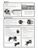
COM
N.C.
N.O.
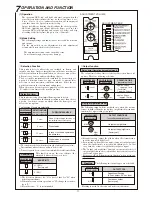
Mounting hole
(knock out)
United band
hole
Push rivet
Screw
Wiring hole
MOUNTING BOX
MOUNTING BASE
66.7mm
2.63
"
3.29
"
83.5mm
φ6×30 Tapping screw
Screw
Wall
Screw
(1) Attention
(2) Wiring Connection
Operation (selectable) :
Contact capacity : 30V (AC/DC)
0.5A or less
detection time + off delay operation
approx. 2 secs. ~ approx. 1 min.
or
detection time + off delay operation
approx. 5 secs. ~ approx. 10 mins.
Dry contact relay output Form C
Power
10V to 30VDC
(non-polarity)
35mA or less
6
The following wiring and installation can be done. Follow the procedures.
INSTALLATION
*
*
*
EXPOSED WIRING
BUILT IN WIRING
(1) Fix to the surface
(1)
(2)
(2)
(3)
(3)
(4)
blue
black
red
yellow
white
【
Wiring distance
】
Power supply
Size of wire used
DC12V
DC24V
1310' ( 400m)
3120' ( 950m)
5250' (1600m)
9800' ( 3000m)
22600' ( 6900m)
38000' (11600m)
NOTE : 1)
2)
0.75mm
2
(φ0.93mm)
1.25mm
2
(φ1.3 mm)
0.3 mm
2
(φ0.65mm)
Maximum wiring distance, when two or
more sets are connected, is calculated by
dividing the above value by number of sets.
The signal line can be wired in the
distance of up to 3,000ft. (1,000m) with
(dia. 0.65mm) telephone wire.
Select the most suitable installation place and way
according to the purpose. (Refer to "3. PRECAU-
TIONS" and the following)
Take off the 2 screws, mounting base, mounting box.
(Wiring leads are contained in the mounting base.)
Wire and instal the sensor.
(Refer to "5. WIRING"
and the following)
Set up temporary and confirm the area and operation.
①
Make a hole through the 4 mounting holes
(knock outs) by a driver etc.
②
Fix the mounting box by the 4
φ
6
×
30
tapping screws to the surface.
Fix the mounting base tightly to the
mounting box by the 2 screws.
Follow the "5. (2) Wiring connection" for wiring. To avoid direct
pressure to the knot, combine the wiring by the accessory Combin-
ing Band and fix it to the inside of the box by
φ
4
×
8 tapping screw.
Preparement (not necessary for following case)
[The mounting base fits 83.5mm and 66.7mm type
built in switch box. However, it needs adjustment
for the following case.]
◎
66.7mm type (beginning set up : 83.5mm)
・
Push out the 2 push rivets from the back side of
the mounting base and put them into the 2 holes
on the outside.
Follow the "5. (2) Wiring connection" for wiring.
Fix the mounting base tightly to the attachment
box by the 2 screws.
Give rain proof treatment such as calking to the top
and side of the mounting base. (It may not stick
according to the surface condition.)
*
Use optional equipments for other installation.
Take off the lid of the wiring hole on the bottom
of the mounting box and pass the wiring
through. (Conduit tube wiring is possible for
the wiring hole is conduit tube screw G16.)
(4)
Turn off power when installing. Hot line work will cause electric shock
and damage.
Lead wiring is required. Follow the proper way.
The wiring lead is contained in the mounting base. Take off the screw,
mounting base, and mounting box when installing.
[1]
[2]
[3]
[4]
Fixing hole
Conduit bushing
Wire connection
Combining band
Tapping screw
Lid


