


34
Page
Installation
Installation Manual
•
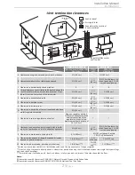
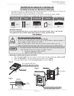
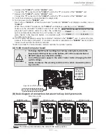
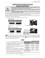
The parent/child DIP switch, No.1 on the lower bank of DIP switches, should be in the OFF
position.
•
T
his is the connection diagram between 510U and multi-unit controller for 2 to 20
water heaters. Above is an example showing seven water heaters.
•
T
he multi-unit controller automatically allocates the unit number (1-20) to each water
heater that is part of the Multi-Unit System.
•
In a Multi-Unit System, connect the “
[1]
” connector and the “
[2]
” connector with the
communication cable (refer to p. 9) or 18 gauge wire cables. The total cable length can
be up to 250 ft (76.2 m) long.
100112691
(TM-MC02)
510U
Cold IN
Hot Out
MULTI-UNIT SYSTEM
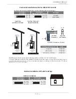
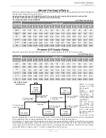
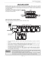
Multiple 510U models can be combined for a Multi-Unit System, along with the multi-unit controller
(Part 100112691 (TM-MC02)). Each multi-unit controller can control from 2 to 20 units for commercial
or residential applications. For a 20-unit system, the computer can modulate from 15,000 BTU/h to
3.98 million BTU/h.
An individual cut-off switch is recommend-
ed for each unit in a Multi-Unit System for
the purpose of maintenance.
Multi-Unit System connection diagram
Multi-unit controller and temperature remote controller wiring:
OFF
ON
1
1
1
2
2
2
PARENT
PARENT
PARENT
1
2
3
4
5
6
Connectors
Connectors
Connectors
OFF
ON
OFF
ON
Lower bank of
DIP switches
Lower bank of
DIP switches
Lower bank of
DIP switches
Lower bank of
DIP switches
Lower bank of
DIP switches
Lower bank of
DIP switches
Lower bank of
DIP switches
1
2
3
4
5
6
1
2
3
4
5
6
Communication cable
Communication cable
Communication cable
Communication cable
Remote controller cable
1
1
2
2
PARENT
PARENT
Connectors
Connectors
OFF
ON
OFF
ON
1
2
3
4
5
6
1
2
3
4
5
6
1
1
2
2
PARENT
PARENT
Connectors
Connectors
OFF
ON
OFF
ON
1
2
3
4
5
6
1
2
3
4
5
6
Remote controller
100112691
(TM-MC02)
Terminals for
water heaters
Remote
controller
terminals
Example : 510U x 7 units
•
For detailed instructions on the multi-unit controller, refer to the instructions
that are packaged with the multi-unit controller.
•
The multi-unit controller allocates random numbering. See the controller
instructions to learn how to renumber the system units sequentially.
NOTICE