


28
Page
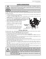
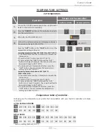
Cold
inlet
Hot
outlet
Gas
inlet
As Close as
Possible
Pressure relief valve
Installation
Installation Manual
4. Before installing the water heater, flush the
water line to remove all debris, and after
installation is complete, purge the air from
the line. Failure to do so may cause damage
to the water heater.
5. There is a wire mesh filter within the cold
inlet to trap debris from entering your heater.
This will need to be cleaned periodically to
maintain optimum flow. (Refer to p. 46.)
All pipes, pipe fittings, valves and other components, including soldering materials, must be suitable for
potable water systems.
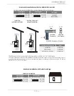
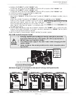
1. A manual shutoff valve must be installed on the cold water inlet to the water heater between the
main water supply line and the water heater.
2. In addition,
a manual shutoff valve
is also recommended on the hot water outlet of the unit.
Isolation valves
are recommended as shown in the picture at right.
3. If the water heater is installed within, or subjected to, a closed
loop water system,
a thermal expansion tank or a code approved
device must be installed to handle thermal expansion.
WATER CONNECTIONS
-Pressure relief valve-
The water heater has a high-temperature shutoff switch built in as a standard safety feature (called a
Hi-Limit switch). Therefore, a
“pressure only”
relief valve is required.
•
This unit does not come with an approved pressure relief valve.
•
An approved pressure relief valve must be installed on the hot water outlet.
•
The pressure relief valve must conform to the current edition of
ANSI Z21.22
or
CAN 1-4.4
and instal-
lation must follow local codes.
•
The discharge capacity must be at least 140,000 BTU/h for the 110U model, 190,000 BTU/h for the
310U model, and 199,000 BTU/h for the 510U model.
•
The pressure relief valve must be rated for a maximum of 150 psi (1 MPa).
•
The discharge piping for the pressure relief valve must be directed so that the hot water cannot splash
outward and cause damage or personal injury.
•
Attach the discharge tube to the pressure relief valve and run the end of the tube to within 6 in.
(152 mm) from the floor. This discharge tube must allow free and complete drainage without any
restrictions.
•
If the pressure relief valve installed on the water heater discharges periodically, this may be due to a
defective thermal expansion tank or defective pressure relief valve.
•
The pressure relief valve must be manually operated periodically to check for correct operation. No
valve shall be placed between the relief valve and the water heater.
Do not use this appliance if any part has been under water. Immediately contact a
qualified installer or service agency to replace a flooded water heater. Do not attempt
to repair the unit! It must be replaced!
WARNING
Do not reverse the hot outlet and cold inlet connections to the water heater. This will
prevent the water heater from activating properly.
NOTICE
WARNING
Hot water could be released when the pressure relief valve is opened. This could
result in severe personal injury. Contact with discharge may cause property dam-
age and/or bodily harm. Before operating the pressure relief valve manually, check
that it will discharge in a safe place. If water does not flow freely from the end of
the discharge pipe, turn the gas supply and power OFF and call a qualified person
to determine the cause.
Refer to the pressure relief valve manufacturer's instructions for inspection and
maintenance requirements.