background image


44

Programming a Dual-Radio System

TM8260 Installation and Programming Guide

© Tait Limited


October 2014

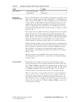
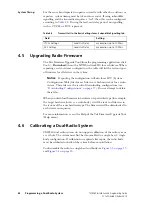
System Timing

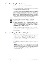
For the cross-band repeater to operate correctly with other base stations or 
repeaters, system timing must be taken into account. If using subaudible 
signalling and the transmitter requires a “tail”, then this can be configured 
according to 

Table 4.5

During the lead-out delay period, no signalling, 

such as CTCSS or DCS, is present.

4.5

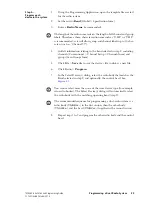
Upgrading Radio Firmware

The Tait Firmware Upgrade Tool (from the programming application, click 
Tools >

Download

) shows the NTID (network ID) for each device. When 

reporting a radio system’s configuration, the table will list the various types 
of firmware for all devices in the system.

Notice

Reporting the configuration will also show SCT (System 

Configuration Table) files for each device, which must exist for a radio 
system. These files are the result of downloading configurations (see 

“Downloading Configurations” on page 17

). Do not attempt to delete 

these files.

When you download firmware to hardware of a particular type (for example, 
the target hardware shows as a radio body), it will be sent to all devices in 
the system of the same hardware type. The firmware will be downloaded to 
each device in sequence.

For more information, access the Help of the Tait Firmware Upgrade Tool 
(Help menu).

4.6

Calibrating a Dual-Radio System

TM8260 dual radio systems do not support calibration of the radio system 
as a whole. The system must first be disassembled to a single head / single 
body configuration. If calibration is required after repair, the radio body 
must be calibrated outside of the system before re-installation.

To disassemble the radio to a single head and body, see 

Figure 3.3 on page 19


and 

Figure 3.4 on page 20

.

Table 4.5

Transmit tail in the Basic Settings form, Subaudible Signalling tab

Field

Setting

CTCSS Settings

Lead-Out Delay

any duration, up to 1000ms

DCS Settings

Lead-Out Delay

any duration, up to 1000ms

Summary of Contents for TM8260

Page 1: ...TM8260 Mobile Radios Installation and Programming Guide MMA 00041 04 Issue 4 October 2014...

Page 2: ...607046 NZ607046 NZ610426 NZ610563 NZ612027 NZ613565 NZ615898 NZ615954 AU2004216984 AU321864 AU321868 AU339127 AU339391 CN1031871 CN1070368 CN200930004199 5 CN200930004200 4 CN200930009301 0 EU00091547...

Page 3: ...Vehicles Powered by Liquefied Petroleum Gas 9 1 10 Non standard Radio Installations 9 1 11 IP54 Protection Class Considerations 10 1 12 Negative Earth Supply 10 2 Preparing the Installation 11 2 1 Ins...

Page 4: ...g the Installation 36 4 Programming a Dual Radio System 37 4 1 Connecting a Dual Radio System to a PC 38 4 2 Programming a Dual Radio System 38 4 3 Recommended Dual Radio Settings 40 4 4 Crossband Rep...

Page 5: ...tion is available for this product MMA 00040 xx TM8260 User s Guide MMA 00028 xx TM8100 TM8200 Installation Guide MMA 00005 xx TM8100 TM8200 Service Manual 402 00030 xx Crossband Linking Cable Install...

Page 6: ...used to draw your attention to information that may improve your understanding of the equipment or procedure Within this manual the following symbols are used to highlight differences between radios w...

Page 7: ...ios must be installed using an antenna mounted either centrally on the roof with a gain of 2 15dBi or 5 65dBi or centrally mounted on the trunk with a gain of 5 65dBi For radios with a transmit power...

Page 8: ...ne to malfunction due to the lack of protection from RF energy when your radio is transmitting Examples of vehicular electronic devices that may be affected by RF energy are electronic fuel injection...

Page 9: ...pace containing the radio equipment shall be isolated by a seal from the space containing the LPG container and its fitting Outside filling connections shall be used for the LPG container and its fitt...

Page 10: ...en a remote interface is removed from the radio body or control head the bungs are removed from the auxiliary connector or the cavity for the external options connector fitting an auxiliary connector...

Page 11: ...wer meter capable of measuring forward and reflected power at the operating frequency of each radio 2 2 Unpacking and Checking the Equipment for Completeness To install a dual radio system you require...

Page 12: ...03 03 remote cable TMAA04 01 and microphone such as rugged TMAA02 01 or keypad TMAA02 08 graphical control head see above with dual head upgrade TMAA11 09 or hand held control head TMAC70 xx radio con...

Page 13: ...code v1 07 Hardware subassembly XMAC31 revision 002b and PCB 220 01720 05 Hardware subassembly XMAC40 revision 009b Hardware subassembly XMAA03 03 revision 003b and PCB 220 01721 04 TM8200 Programmin...

Page 14: ...face cable 1 to control head such as graphical display see example or hand held e radio body f body remote interface with link J4 fitted Control head example g grommet 1 control head remote cable h ra...

Page 15: ...e of the corners of the microphone grommet Firmly but gently pull that corner until the seal comes away from the cavity See Figure 2 2 Figure 2 2 Removing a grommet 2 Repeat to expose another corner 3...

Page 16: ...Download NTIDs to all devices in the system See Downloading Configurations on page 17 3 Remove link J4 from the radio body interface that will be connected to the control head See Removing Link J4 on...

Page 17: ...nal Features 3 3 Downloading Configurations Every device head and body in a TM8260 radio system must have a system configuration table SCT downloaded with unique NTID network ID addresses Figure 3 1 T...

Page 18: ...tem The entire table must be downloaded to each device not just informa tion about the device that the table is intended for See Figure 3 1 3 Connect the control head directly to the radio body that y...

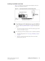
Page 19: ...onnecting a control head with graphical display see Figure 3 4 diagram b or diagram c 8 If connecting a hand held control head see Figure 3 4 diagram d Figure 3 3 UHF radio body connected directly to...

Page 20: ...ead to a radio body and repeat step 10 for device TMACxx with the higher NTID 11 Check that all red indicators in the table are now green Figure 3 4 VHF radio body connected directly to the control he...

Page 21: ...tion is required at the ends of an RS485 network In the case of a TM8260 dual radio system the radio body with the two connections to the control head and to the other radio body is a node on the netw...

Page 22: ...able to inspect and if necessary remove shorting link J4 It is not necessary to remove the body interface loom or the earthing tag to remove the link Assembling the Body Remote Interfaces The followi...

Page 23: ...the preferred mounting method such as U brackets slide in cradles or security brackets For more information refer to the instructions included with the cradle or bracket installation kit Installing th...

Page 24: ...e outermost port of the radio body with link J4 removed The innermost port of this radio connects to the control head solution 3 Attach the other end of the radio connecting cable to the innermost por...

Page 25: ...ional equipment such as filters if your installation environment does not allow for proper separation the channel frequencies of the two radios are similar or after testing you experience poor perform...

Page 26: ...the roof with a gain of 2 15dBi or 5 65dBi or centrally mounted on the trunk with a gain of 5 65dBi For 25W radios The radio must be installed using an externally mounted antenna with a gain of either...

Page 27: ...o to the center tap of two 12V batter ies This may result in damage to the radio due to earth loops in partic ular when the negative lead is disconnected from the vehicle battery It may also result in...

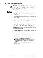
Page 28: ...ery is not disconnected exercise extreme caution during the installation and install the fuses only when the installation is ready to be checked For more information refer to Checking the Installation...

Page 29: ...itive wire 8 Connect the negative wire to the battery ground terminal 9 Connect the positive wire to the battery positive terminal 10 Repeat steps 2 to 9 for the other radio body Notice Do not install...

Page 30: ...e power connector are provided with the installation kit The installation kit also contains a flying lead connector that when installed enables the speaker to be easily removed and re installed as req...

Page 31: ...ector and GPS socket are closest to the device or devices to connect to 4 Tightly fasten the jackscrew type locks 5 If your cable has additional connectors refer to the installation instructions for y...

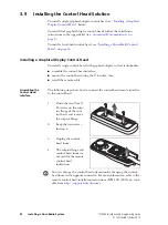
Page 32: ...ay to dual radio bodies assemble the control head interface mount the control head using the U bracket then install the remote cable Assembling the Control Head Interface The following steps show how...

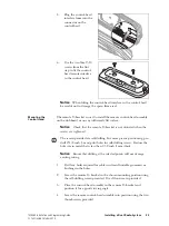
Page 33: ...the selected points will not damage existing wiring 1 Drill any holes required for cables and install suitable grommets or bushings in the holes 2 Screw the remote U bracket in the chosen mounting pos...

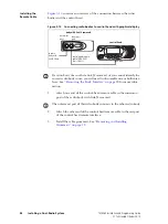
Page 34: ...for more infor mation 1 Attach one end of the control head remote cable to the innermost port of the radio body with link J4 removed The outermost port of this radio body connects to the other radio b...

Page 35: ...ce on page 22 for more infor mation 1 Attach the hand held control head cord to the innermost port of the radio body with link J4 removed The outermost port of this radio body connects to the other ra...

Page 36: ...evels Less than 4 of the forward power should be reflected If this is not achieved check the installation including the antenna length 5 Start reducing the length of the antenna in steps of 0 1 inches...

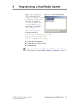
Page 37: ...ate with the radio system the Select Device s dialog appears an example is shown in Figure 4 1 This section contains the following information Connecting a Dual Radio System to a PC Programming a Dual...

Page 38: ...control head but using the microphone port of the primary control head To identify the primary control head select Menu Radio settings Radio info Multi head info For more information refer to the ins...

Page 39: ...selected in step 2 including channels Conventional Channel Setup Channels form and groups Scan Groups form 5 Click File Save As to save the device s file to disk as a new file 6 Click Radio Program 7...

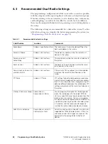
Page 40: ...n the system Reset on Error Global Start up form The Reset on Error check box must be the same for all devices in the system Security Lock on Power Up and Security PIN Global Start up form If the secu...

Page 41: ...es the RSSI icon and the default dialling type Programmable I O Programmable I O form All radio body I O pins are supported and all actions are supported except the output F1 to F4 Key Status The cont...

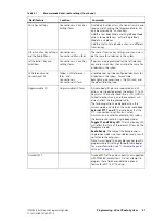
Page 42: ...t Table 4 3 to re transmit any signal 2 Select Signalling Audio Mute Status Table 4 2 and Busy Detect Subaud Table 4 3 to transmit valid signalling only This is recommended if the repeater is to opera...

Page 43: ...the group is captured the radio will re transmit that activity and the transmit timer will begin counting down However each time the radio samples the priority channel or channels there is a brief br...

Page 44: ...are the result of downloading configurations see Downloading Configurations on page 17 Do not attempt to delete these files When you download firmware to hardware of a particular type for example the...

Page 45: ...head single body system and use the programming application s multiple device configuration utility to change the NTIDs click Tools Download and then Device Configuration Advanced For more information...

Page 46: ...on page 21 The remote interfaces are installed on the radio bodies and control head See page 22 and page 32 For each body remote interface the earthing tag is attached onto the radio chassis See page...

Page 47: ...mponent control head or radio body in a radio system A device is known as target hardware when upgrading radio firmware dual body mode The function on a dual radio system that enables you to turn on d...

Page 48: ...system See dual radio system single body mode The function on a dual radio system that enables you to return to single receive and single transmit single receive and single transmit A state in a dual...

Page 49: ...to the Software and Docu mentation including any adaptations correc tions de compilations disassemblies emula tions enhancements fixes modifications translations and updates to or derivative works fr...

Page 50: ...f the Software at the same time as the original Software is being operated Licensee may make as many copies of the Documenta tion as it may reasonably require for the internal use of the Software 4 3...

Page 51: ...the related Documentation provided that Licensee transfers all copies of the Software and Documentation to the transferee 7 4 For the avoidance of any doubt Section 7 3 excludes TaitNet Infrastructur...

Page 52: ...eficiary of this Agreement Not withstanding the foregoing any licensor or supplier of third party software included in the Software will be a direct and intended third party beneficiary of this Agreem...

Reviews: