

8.16.6
T2000-A03/-A04/-A16 Remote Loom Kits
M2000-00
31/12/97
Copyright TEL
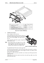
8.16.3 Fitting To Remote Mounted Radios
1
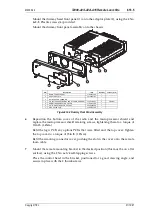
Refer to Figures 8.16.2, 8.16.3 & 8.16.4.
Remove the radio dummy front panel (1) by removing the 4 dummy front panel
screws (4).
Note:
In later T2000 radios, the radio dummy front panel is fitted with a remoting
connector cover (3). This is unclipped to access the remote loom connector.
When fitting a remote loom, it is therefore unnecessary to remove the dummy
front panel.
Unplug the old remote loom from the connector PCB (Series I chassis) or EMC fil-
ter PCB (Series II chassis).
Series II chassis:
Check that the top side connector (SKT-1) on the EMC filter PCB
is 8 way. If not, discard the existing filter PCB and fit the new PCB provided in the
kit (refer to Section 8.16.2, “Fitting To Locally Mounted Radios”, step (5)).
If necessary, replace the old dummy front panel with the new dummy front panel,
complete with remoting connector cover, provided in the kit.
Pass the new remote loom through the connector cover hole in the dummy front
panel, and plug the 8 way remote loom connector onto the 8 way connector (6) on
the connector PCB or EMC filter PCB.
T2000-A16:
Fit the remote loom drain wire solder tag under one of the connector
PCB or EMC filter PCB screws.
Mount the dummy front panel onto the adaptor plate (2), and secure in place
using the 4 dummy front panel screws.
Refit the remoting connector cover, pushing the slot in the cover onto the remote
loom cable.
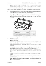
2
Refer to Figure 8.16.1.
Remove the control head remote back panel (2) by removing the 4 remote back
panel screws (5), taking care not to loose the captive nuts (4). EMC model radios
will also have ESD plugs (7) over the remote back panel screws.
Note:
In later T2000 radios, the control head remote back panel is fitted with a remot-
ing connector cover (3). This is unclipped to access the remote loom connector.
When fitting a remote loom, it is therefore unnecessary to remove the remote
back panel.
Unplug the old remote loom from the 8 way connector on the control head PCB (6).
If necessary, replace the old remote back panel with the new remote back panel,
complete with remoting connector cover, provided in the kit.
Pass the new remote loom through the connector cover hole in the remote back
panel, and plug the 8 way connector on the new remote loom onto the 8 way con-
nector on the control head PCB.
T2000-A16:
Fit the remote loom drain wire solder tag under one of the control
head PCB screws.
Note:
Ensure that the solder tag does not make contact with any devices in the control
head.
Summary of Contents for T2000 SERIES II
Page 64: ...7 9 2 T2000 TCXO Tx Audio PCB M2000 00 31 10 96 Copyright TEL IPN 220 01389 00 ...
Page 66: ...7 9 8 T2000 TCXO Tx Audio PCB M2000 00 31 12 97 Copyright TEL IPN 220 01389 02 ...
Page 94: ...7 14 4 T2020 T2040 T2050 Control Head PCB M2000 00 31 10 96 Copyright TEL IPN 220 01321 04 ...
Page 98: ...7 16 2 T2000 EMC Filter PCB M2000 00 31 10 96 Copyright TEL IPN 220 01383 01 ...
Page 100: ...7 17 2 T2000 Data Interface Decoupling PCB M2000 00 31 10 96 Copyright TEL IPN 220 01388 01 ...
Page 102: ...8 2 Accessories M2000 00 31 12 97 Copyright TEL ...
Page 110: ...8 10 6 T2000 A450X CTCSS Scrambler Kit M2000 00 31 12 97 Copyright TEL ...
Page 113: ...M2000 00 T2000 A450X CTCSS Scrambler Kit 8 10 9 Copyright TEL 31 12 97 ...
Page 114: ...8 10 10 T2000 A450X CTCSS Scrambler Kit M2000 00 31 12 97 Copyright TEL ...
Page 124: ...8 13 8 T2000 A66 Single Port UART Kit M2000 00 31 12 97 Copyright TEL ...
Page 141: ...M2000 00 T2000 A70 Data Modem Kit 8 15 17 Copyright TEL 31 12 97 ...
Page 142: ...8 15 18 T2000 A70 Data Modem Kit M2000 00 31 12 97 Copyright TEL ...
Page 150: ...8 16 8 T2000 A03 A04 A16 Remote Loom Kits M2000 00 31 12 97 Copyright TEL ...


