


5 MODBUS ASCII Protocol
FY400/600/700/800/900 COMMUNICATION MANUAL
7
5 MODBUS
ASCII
Protocol
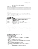
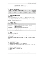
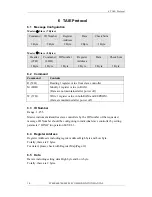
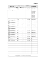
5.1 Message
Configuration
Header
(:)
1 Byte
ID Number
2 Byte
(Function Code)
2 Byte
Data
2N Byte
LRC
2 Byte
Delimiter
(CR+LF)
2 Byte
5.2 ID
Number(Slave
Address)
Range: 1~255
Master instrument identifies slave controllers by the ID Number of the requested
message. ID Number should be configuring in individual slave controller by setting
parameter “IDNO” in operation LEVEL 3.
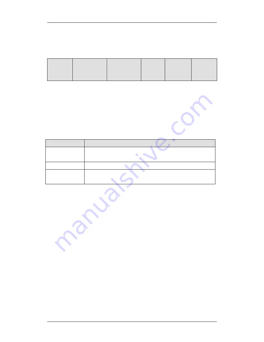
5.3 Function
Code
Function Code
Contents
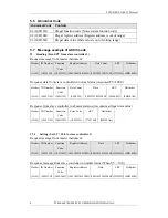
03 (30H 33H)
Reading multiple registers value from slave controller
(Max register count : 8)
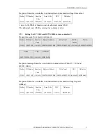
06 (30H 36H)
Setting 1 register value to slave controller
16 (31H 30H)
Setting multiple registers value to slave controller.
(Max register count : 8)
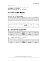
5.4 Data
Data depends on function code.
Request message from Master instrument is include “register address”, “data count”
and “setting data”.
Response data from Slave controller is include “byte count”, “data” and “abnormal
code”.
5.5 Error Check LRC
LRC generation step is as below:
①
.
Convert all the messages to RTU mode (HEX code)
。
②
.
Add all the values from “ID Number” to the end of “Data”. This is assumed as
Y(8Bit).
③
.
Calculate 2’s complement with Y.
④
.
Convert Y to ASCII characters (16 bit)
⑤
.
LRC=Y


