background image

3

Tahoe 8216 / Tahoe 8116  Remote Power Management System

Tahoe 8116

Th

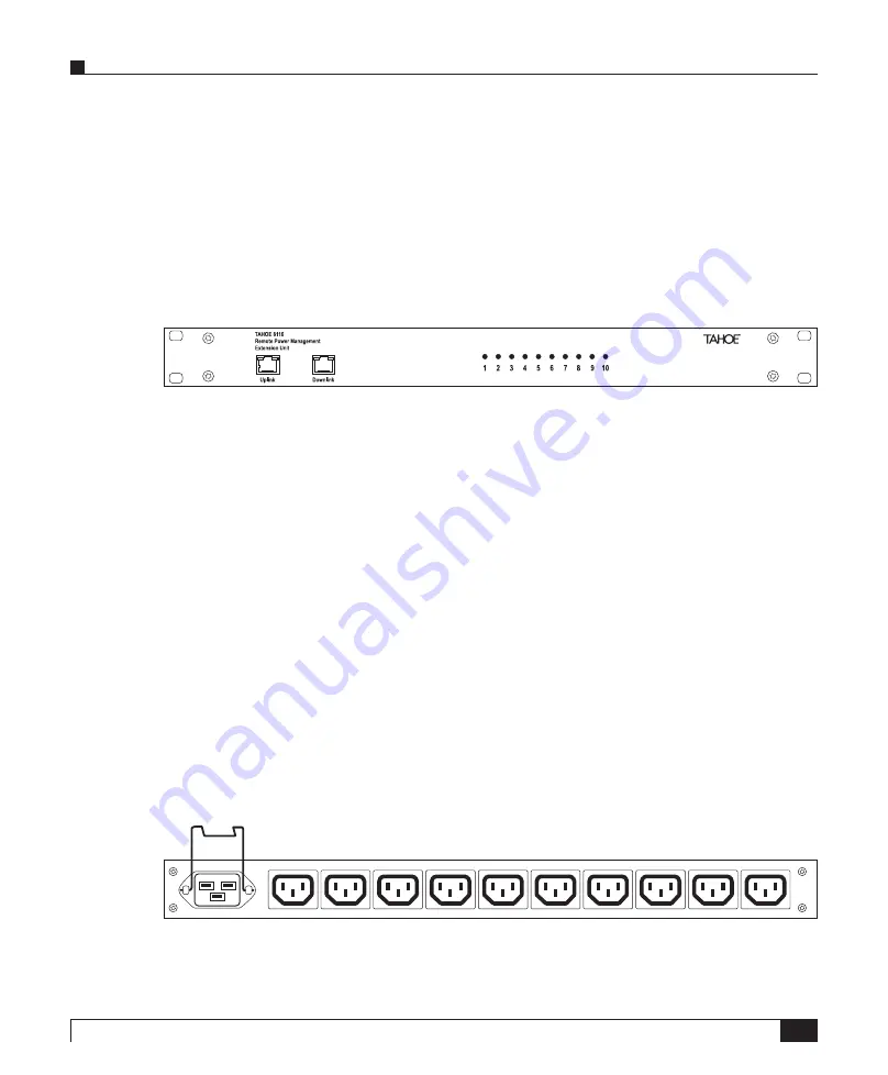
e Tahoe 8116 is the Tahoe Remote Power Management System Extension Unit device. It is a cost-

e

ff

ective solution to extend the number of available power outlets of the Tahoe 8216. Each extension 

unit contains 10 additional power outlets. 

Th

e whole chain of Tahoe 8216 and Tahoe 8116 devices is 

controlled by the main Tahoe 8216 unit.

Tahoe 8116 Front Panel

LED indicators

Ten LED indicators display the state of the corresponding outlets. 

Uplink

Used to connect to a master device in a chain. Should be connected to the master’s Downlink port.

Downlink

Used to connect a slave device in a chain. Should be connected to the slave’s Uplink port.

Rear Panel

Th

e back panel looks the same for both the Tahoe 8216 and the Tahoe 8116 Extension Unit.

Th

e rear panel contains one IEC 60320 C20 power inlet and ten independently controlled IEC 60320 

C13 power outlets. 

Summary of Contents for 8116

Page 1: ...User Manual Tahoe 8216 8116 Remote Power Management System ...

Page 2: ......

Page 3: ...User Manual Tahoe 8216 Tahoe 8116 Remote Power Management System ...

Page 4: ...CURATE BUT ARE PRESENTED WITHOUT WAR RANTY OF ANY KIND EXPRESS OR IMPLIED AND TAHOE MAKES NO COMMITMENT TO UPDATE THE INFORMATION CONTAINTED HERE NOTWITHSTANDING ANY OTHER WARRANTY HEREIN ALL DOCUMENT FILES AND SOFTWARE OF THESE SUPPLIERS ARE PROVIDED AS IS TAHOE DISCLAIM ALL WARRANTIES EXPRESSED OR IMPLIED INCLUDING WITHOUT LIMITATION THOSE OF MERCHANTABILITY FITNESS FOR A PAR TICULAR PURPOSE AND...

Page 5: ...use no larger than 240 VAC 16A is used Check nameplate ratings to ensure there is no overloading of supply circuits that could have an effect on overcurrent protection and supply wiring There is no physical circuit separation if the outlet is disabled Always disconnect the power cord be fore removing the cover of any powered device Immediately disconnect the unit from the outlet and contact qualif...

Page 6: ...ervice Tahoe 8216 GSM only 5 Chaining Tahoe 8116 5 Configuration and Management 6 LCD Menu 6 Remote Connection 7 Web Interface 7 Telnet Connection 9 SSH Connection 10 GSM access Tahoe 8216 GSM only 10 Serial Console 11 Command Line Interface 11 Appendix A Troubleshooting 23 Appendix B Technical Specification 25 Appendix C Declaration of Conformity 27 ...

Page 7: ...How to install Tahoe 8216 and 8116 extension unit Chapter 3 Advanced Configuration and Management Ways to access and manage the device list of available commands Appendix A Troubleshooting Description of typical problems that may occur during use of the device Appendix B Technical Specification Technical parameters of the device Appendix C Declaration of Con formity Information about compliance wi...

Page 8: ...ter font Information to be entered during a management session LCD font Information displayed on the LCD Note Notes contain helpful suggestions that may be worth remembering Caution This symbol means a situation that requires you to be careful Otherwise equipment damage or loss of data may occur Warning This warning symbol means danger You are in a situation that could cause bodily injury Before y...

Page 9: ...r control even in situations where the whole network is inaccessible We did our best to ensure the highest standards of reliability and performance of our products Having devoted many years of research and development we are proud to provide a superior qual ity product unfolding new possibilities Tahoe 8216 The Tahoe 8216 is the main unit of the Tahoe Power Management System It allows the user to ...

Page 10: ...C a router or an uplink port in a switch using a crossed over cable After connecting the cable the Link LED should light up Status LEDs The following status LEDs are placed on the front panel LINK lit when the device is connected to a LAN LAN Act LAN activity blinks when data is sent or received 10 100M LAN connection throughput lit when 100 Mbpsconnection speed is negotiated GSM GSM status off GS...

Page 11: ... controlled by the main Tahoe 8216 unit Tahoe 8116 Front Panel LED indicators Ten LED indicators display the state of the corresponding outlets Uplink Used to connect to a master device in a chain Should be connected to the master s Downlink port Downlink Used to connect a slave device in a chain Should be connected to the slave s Uplink port Rear Panel The back panel looks the same for both the T...

Page 12: ...oduct relies on the building s installation for short circuit overcurrent protection Ensure that a fuse no larger than 240 VAC 16A is used Mounting 1 Position the device in the rack and align the holes in the mounting brackets with the holes in the rack 2 Tighten the device to the rack using four screws 3 Install the power cord retention bracket 4 Attach the power cord and lock the retention brack...

Page 13: ... slot as shown See GSM access section in the Configuration and Management chapter to configure GSM access Chaining Tahoe 8116 To connect the Tahoe 8116 Extension Unit connect its Uplink connector with the master device Downlink connector using a straight patch cord cable The connector s LED should light up The remaining Downlink connector may be used to connect another extension unit ...

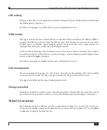
Page 14: ...ion is unavailable LCD Menu The LCD display shows the current state of the device and the build in keyboard allows the user to change the state of outlets and gives quick access to basic settings The default LCD screen displays the main unit s state Tahoe 1 2 3 231V 6 7 9 10 The displayed numbers indicate enabled outlets while a dot means that the corresponding outlet is disabled In the bottom lef...

Page 15: ...ith its name and state displayed Press Enter to change outlet state as described above e g 1 1 Outlet1 Enabled Remote Connection By default the device has the address 10 0 0 1 netmask is 255 0 0 0 and there is one user account named root with the default password Tahoe case sensitive To connect to the device the network interface on the remote host has to be on the same IP subnet as the device so ...

Page 16: ...be saved anytime by clicking Save Settings on the top panel You may also reboot the device by clicking Reboot or logout by clicking X on the top panel By default HTTP occupies TCP port number 80 Use the http command to configure the web service Power management The power management page presents a list containing the main unit and chained extension units if any For each unit total power consumptio...

Page 17: ... associations using the Add and Remove actions Messages received from associated numbers don t need to contain the login command The GSM service page is available only for users of administrative level User management The user management page presents a list of users For each user his privilege and actions available are shown The user name privilege and password may be changed with an Edit action ...

Page 18: ...b interface or the gsm pin command and settings saved afterwards Also make sure the GSM service centre to be used is correctly set The outlets are controlled via short text messages using the following commands login username password on outlets off outlets reset outlets end The login command is needed to authenticate the sender preceding other commands if their number is not in the list of known ...

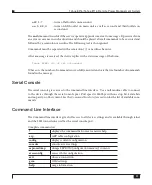
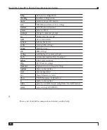
Page 19: ...ecuted and m is the total number of commands found in the message Serial Console The serial console gives access to the command line interface Use a null modem cable to connect to the device through the serial console port Port speed is 9600bps with one stop bit 8 data bits and no parity no flow control See the Command Line Interface section for the list of available com mands Command Line Interfa...

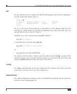
Page 20: ...ts the device route routing table settings snmp SNMP settings ssh SSH settings syslog sending logs to remote syslogd tech system information for tech support telnet telnet server settings tftp TFTP server settings timeout login and session timeout settings uptime shows router uptime user user management ver shows firmware version vlan VLAN bridging configuration w shows router uptime wake powers o...

Page 21: ... entries can be removed using the arp del command arp del IP address A static ARP entry can be added using arp add arp add IP address MAC address e g arp add 10 0 0 4 00 50 13 E9 5C 01 The dynamic hardware address resolution may be disabled using the ifconfig command When disabled only those stations whose IP and MAC addresses are entered statically into the ARP table using the arp add command are...

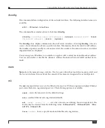
Page 22: ...mmand exit This command closes the session and disconnects the user from the device help Shows usage information http The http command configures the built in web server The server can be enabled or disabled by entering respectively http on or http off The web server port may be changed with http port port The default port is 80 Access to the server can be limited by entering http host IP address ...

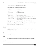
Page 23: ...an IP address to an interface together with a subnet mask and broadcast address You can also enable or disable the dynamic Address Resolution Protocol ARP enabled by de fault mem Mem shows the memory usage statistics The free entry shows how much free memory is left and the free bufs informs the user about the amount of free memory designated for network packets mii The mii command allows access t...

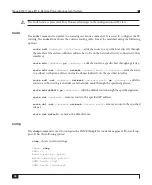
Page 24: ...shown with power usage information active power current voltage and frequency for each unit The following options are available status outlets shows the state of all or selected outlets on outlets enables selected outlet s off outlets disables selected outlet s reset outlets resets selected outlet s rename outlet new name outlets assigns a name to outlet s rename unit new name unit assigns a name ...

Page 25: ... second and third out lets on second unit Using the power watch command you may assign an IP address to a specific outlet s In this case the outlet is reset if the specified address doesn t respond to ICMP echo requests The echo request is sent every interval seconds If the amount of consecutive echo requests are not replied to the outlet reset is performed After boot or reset echo requests are no...

Page 26: ...te add net address netmask network mask interface adds the route to a subnet with given address and network mask directly on the specified interface route add net address netmask network mask gw gateway adds the route to a subnet with given address and network mask through the specified gateway route add default gw address adds the default route through the specified gateway route del address remo...

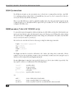
Page 27: ...esses from which SNMP access will be permitted Entering 0 0 0 0 allows access from any address while 255 255 255 255 disa bles an entry entering 255 255 255 255 in all three positions is equal to disabling the SNMP service ssh The ssh command configures the built in Secure Shell server The server can be enabled or disabled by entering respectively ssh on or ssh off For the first time when the serv...

Page 28: ...ess sets the IP address to which the messages will be sent tech The tech command displays a detailed report about the device s internal state This output may be used by the technical support for debugging purposes telnet This command allows limiting telnet access to the device Access may be enabled or disabled by entering telnet on or telnet off respectively The telnet port may be changed with tel...

Page 29: ...eover access may be limited to a certain IP address tftp host IP address If the IP address is set as 0 0 0 0 then access is possible from anywhere in the network timeout This command sets the inactivity time in seconds after which the remote connection is closed Tahoe timeout session timeout loggin timeout The first parameter is used after logging in while the second one optional is used during th...

Page 30: ...ince the device boot wake The wake command is used to power on LAN devices that have the Wake On LAN ability To send a wake up packet to a specified MAC address type wake b MAC address A b option may be added before the MAC address to generate a broadcast packet This may be necessary in some cases when the regular packet isn t forwarded through the Ethernet switch or another device write Saves the...

Page 31: ...N is entered and saved Make sure the correct login command is entered or the sender is in the list of known numbers Make sure the GSM antenna is properly fastened to the RF connector Check the GSM signal level and use an external antenna if necessary The 8116 Extension Unit is not visible Make sure the extension unit Uplink socket is connected to Downlink on the master device with a straight patch...

Page 32: ...z memory 4MB SDRAM connectors LAN RJ 45 Console DB 9 M Downlink RJ 45 Uplink RJ 45 Downlink RJ 45 RF SMA SIM Card GSM EGSM 900 1800 850 1900 Mhz network protocols IP TCP UDP ICMP TFTP SNMP SSH HTTP Ethernet interface 10 100Base T RJ 45 connector serial console RS 232 DB 9 M connector power consumption 20W 25W 8W dimensions 483 mm width x 44 mm height 1U x 291 mm depth environmental conditions stor...

Page 33: ...and Tahoe 8116 with the requirements of the above mentioned directives is ensured by the complete application of the following harmonized European Standards EN 60950 2000 EN 55022 1998 EN 61000 6 1 2002 EN 61000 6 3 2002 The products also comply with the directive 2002 95 EC on the restriction of the use of certain hazardous substances in electrical and electronic equipment RoHS Directive with the...

Page 34: ...26 Tahoe 8216 Tahoe 8116 Remote Power Management System ...

Page 35: ......

Page 36: ...Hercena 3 5 50453 Wrocław Poland phone 48 71 344 26 37 fax 48 71 344 26 42 www tahoe group com ...

Reviews: