


XT-1 Installation Manual
13-111 02, 2014-RO-012, 2014-04-30
Page 17 of 32
Inputs
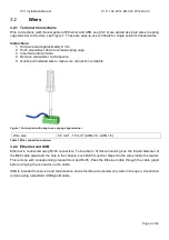
The XT-1 has 3 software configurable inputs. The inputs are opto-coupled, have 1500 VDC isolation and
reverse polarity protection. The inputs are activated by a current flow and the input impedance is 1 k
Ω
. A
schematic view of an input is shown in Figure 18. The software functionality is described in §4.2.3.3.4.
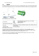
Figure 17 Input connections, overview and detail
Connections
IN1+
Input 1 positive terminal
IN1-
Input 1 negative terminal
IN2+
Input 2 positive terminal
IN2-
Input 2 negative terminal
IN3+
Input 2 positive terminal
IN3-
Input 3 negative terminal
High Voltage (active)
Min 3.0 V / Max 30 V
Low Voltage (inactive)
Min 0.0 V / Max 0.2 V
Input impedance
1 k
Ω
Recommended / Max length
10 m / 100 m
Wire size
0.5 mm
2
(AWG 20)
Table 9 Input connection overview
Figure 18 Input schematic


