

2
missprints and technical changes reserved
Instruction & Operating Manual
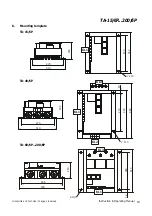
TA-15/6P...200/6P
r
Full controlled three phase bridge
r
Field Current control
r
Phase control
r
Blocking control
r
Current Output Impulse controlled
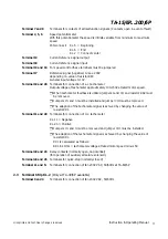
2.
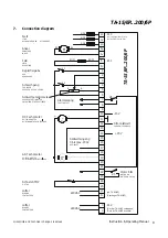
Connection of the drive control
(refer to connection diagram TA-15/6P...200/6P)
Ensure that your line voltage corresponds to the voltage indicated on the type marking of the unit.
2.1 Terminal Strip KL. 3
(at TA-15/6P KL.3=KL.1)
L1 - L2 - L3
Three phase a.c. line input and voltage according to type marking on unit.
Frequency see the selector switch on the upper printed circuit board.
A+ A-
Armature
2.2 Terminal Strip KL. 1
F+ F-
Field
Terminal 1 and 9
Drive ON - (Closing contact)
(Drive remains switched on until contacts open)
Terminal 4 and 9
Jog Speed ON - (Closing contact)
(Drive remains switched on until contacts open)
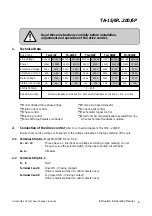
1.
Technical Data
r
Motor-Zero Speed Indicator
r
Current Limit control
r
Tachometer Signal control
r
Electronic circuit galvanically seperated from line
when tachometer feedback is utilized
Drive Type
TA-15/6P
TA-40/6P
TA-60/6P
TA-100/6P
TA-200/6P
Line Voltage
230VAC 400VAC 230VAC 400VAC 230VAC 400VAC 230VAC 400VAC 230VAC 400VAC
Power
10KW
15KW
24KW
40KW
35KW
60KW
60KW
100KW 120KW 200KW
Armature Voltage
240V
440V
240V
440V
240V
440V
240V
440V
240V
440V
Armature Current
45A
45A
100A
100A
180A
180A
280A
280A
560A
560A
Field Voltage
155V
270V
155V
270V
155V
270V
155V
270V
155V
270V
Field Current max
4A
4A
4A
4A
10A
10A
10A
10A
10A
10A
Ambient Temp.
0 - 40 °C
Speed Accuracy
Armature feedback controlled 3% - Tachometer feedback controlled a.c 2% ; d.c 0,5%
Read these instructions carefully before installation,
adjustment and operation of the drive control.


