Tactec TAC 310SX Programming Instructions Manual Download Page 8

4.  Make  sure  the  computer  Is  turned  off.  Plug  the  programming  cartridge,

face up,  into  computer's  expansion  slot. 

It  1s  the  largest  slot  on  the

back of  the  computer  and  the  only  port  Into  which  the  cartridge will  fit.

Seat the  cartridge  firmly  Into  the  connector.

5.  Turn  the  computer  on.  Within  30  seconds  the  normal  start-up  message  (see

page  7)  should  appear on  the  television  screen.  If  It does  not,  remove  the 

cartridge  and  check  to  make  sure  that  only  the  BLOCK  5  rocker  on  the  DIP 

switch  Is  set,  with  all  other  rockers  unset.  If  the  normal  start-up  me s­
sage  does  not appear with  the  rockers  properly  set,  the cartridge  Is  defec­
tive.  Return  It  for exchange.

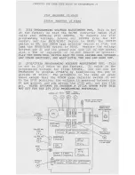
6.  After  the  start-up  message  appears,  see  that  the  green  LED  glows  to  indi­

cate  that  the  zero  insertion  force  (ZIF)  EPROM  socket  1s  connected  to  the 

computer  and  is  receiving  power.  Flip  the  SOCKET  switch  OFF.  The  green 

light  should  go  out.  It  is  then  be  safe  to  Install  an  EPROM  In  the  socket, 

or  remove  one  already  Installed,  without  turning  off  the  computer.  Don't 

install  any  EPROMs  now.  Flip  the  SOCKET  back  to  the  ON  position.  Leave 
the  socket empty.

CAUTION

Turn  OFF  the  socket  switch whenever you  change  EPROMs.

7.  Ttie  MIMIC/PROG  switch  located  below  the  SOCKET switch has  two  functions:

a.  the  PROG  position  enables  the  computer  to  operate  with  the  programming 

cartridge.

b.  the  MIMIC  position  enables you  to jumper  to  an external  computer.

If you  flip  the  switch  to  MIMIC,  the  green  LED  goes  out.  The  MIMIC  posi­

tion  1s  not  used  In  this  application. 

For  now,  set  the  switch  back  to 

PROG,  and  observe  that  the  green  LED comes  back  on.

CAUTION

Always  make  sure  that you  have  this  switch  set  to  PROG.

8.  The  toggle  to  the  right  of  the  MIMIC/PROG  switch  is  the  EPROM  select 

switch.  This  switch  may  be  set  to  read  and  program  either  2716  or  2732 
EPROMs.

CAUTION

Always make  sure  that you  have  this  switch  set  for  the 

proper  EPROM  type  before you  burn  an  EPROM.  Otherwise, 

you will  probably  damage  the  EPROM.  No  damage will  occur 

if you  have  the  switch mls-set  in  the  normal  PROG mode.

Flip  the  2716/2732  switch  to  the  2732  position.

9.  The  upper  right  toggle  has  two  modes: 

BURN  and  PROG.  When  set  to  BURN,

this  switch  enables  you  to  BURN your  own  program  onto  an  EPROM.  The  RED 
LED will  come  on,  Indicating  that  programming  voltage  1s  being  supplied  to 
the  EPROM  socket.  With  no  EPROM  In  the  socket,  test  the  BURN  switch  by 

slipping  It  away  from  you.  A  faint  buzzing  noise  made  by  the  cartridge 

may  be  audible  when  the  red  LED  1s  on.  H u s   Is  normal.  Notice  that  the 

red  LED  will  go  out,  along  with  the  green,  If  you  now  flip  the  SOCKET 

switch  to  OFF,  or  If you  flip  the  PROG/MIMIC  switch  to MIMIC.

-8-

Summary of Contents for TAC 310SX

Page 1: ...TAC 310SX A 14 or 16 channel synthesized VHF or UHF mobile radio small enough for dashmounting EPROM Programming Instructions Y j ov TACTEC SYSTEMS INCORPORATED...

Page 2: ...nsertion force ZIF socket 1s not present in the equipment use an EPROM IC puller or a small bladed screwdriver to alter nately pry up one end then the other prying a small amount at a time PROPRIETARY...

Page 3: ...omputer to theTelevision Set 6 To Avoid Confusion About theD i s p l a y 7 Plugging 1n the ProgrammingCartridge the First T i m e 7 Loading the Master EPROM 9 Main M e n u 9 Starting O v e r 10 Ttie F...

Page 4: ...VIC 20 CONTROLS AND PORTS FUNCTION KEYS GAME PORT ON OFF POWER POWER SOCKET not u cf SWITCH LIGHT attach power supply her 4...

Page 5: ...ERTION FORCE ZlF EPROM SOCKET BLOCK SELECT SWITCH set to BLOCK 5 at shown Use the switch numbers embossed on the case not the ones on the switches EDGE CONNECTOR plugs into computer Expansion Port CAU...

Page 6: ...keyboard comfortably while viewing the television screen 2 Make sure the ON OFF switch on the right hand side of the computer is OFF 3 Plug the power supply cord Into an electrical outlet and then plu...

Page 7: ...PLAY Please note 0 the letter 0 as in Open 0 ZERO 1 the letter I as in Input 1 the number ONE Cursor PLUGGING IN THE PROGRAMMING CARTRIDGE THE FIRST TIME 1 Pick up the programming cartridge If an EPRO...

Page 8: ...switch has two functions a the PROG position enables the computer to operate with the programming cartridge b the MIMIC position enables you to jumper to an external computer If you flip the switch t...

Page 9: ...set 3 Unlatch the EPROM socket by pulling up on the handle with the green knob REMEMBER Turn OFF the socket switch whenever you change EPROMs 4 Place the master EPROM Into the EPROM socket notched en...

Page 10: ...making changes in the frequency list STARTING OVER RIJN You can always return to the main menu like this Press Tnp type RUN then press RETURN THE FREQUENCY LIST INITIALIZE If all of the frequencies a...

Page 11: ...programmed EPROM in the ZIF socket notched end away from you Turn the SOCKET switch ON REMEMBER Turn OFF the socket switch whenever you change EPROMs Be sure the notched end of the EPROM faces away f...

Page 12: ...channel number you wish to edit then press RETURN 3 The display then switches to the transmit edit menu as follows EDIT CHANNEL N TX FREQ MHZ FROM NNN NNNN TO 4 Type in the new channel frequency or N...

Page 13: ...again using the correct information Continue editing until all channels have been properly listed When you have finished editing Press RETURN when the screen prompts EDIT CHANNEL The display will retu...

Page 14: ...EPROM press function key fl The computer will return to step 4 above Pressing function key f3 will return the computer to the previous menu b If the EPROM is blank you may proceed with the programmin...

Page 15: ...NN NNNN NNN NNNN 4 NNN NNNN NNN NNNN 5 NNN NNNN NNN NNNN 1 NNN NNNN NNN NNNN 2 NNN NNNN NNN NNNN 3 NNN NNNN NNN NNNN 4 NNN NNNN NNN NNNN 5 NNN NNNN NNN NNNN 1 NNN NNNN NNN NNNN 2 NNN NNNN NNN NNNN 3 N...

Page 16: ...YPE PRIOR TO PROGRAMMING 2732 REQUIRES 25 VOLTS 2732 A REQUIRES 21 VOLTS PROM QUEEN VOLTAGE MUST BE SET PROPERLY OR PROM CAN BE DAMAGED UNIT MUST BE RE TUNED AFTER PROGRAMMED EPROM INSTALLED R E F E R...

Page 17: ...ogrammer B Turn on the computer and the programmer C Lake certain that there is no EFBQf in the socket B Set Burn frog switch to 3urn E Adjust ueen I Adjust for the desired voltage F 3et Burn Prog swi...

Page 18: ...h a V O M o f i m p e d a n c e o f 10 000 O h m s V o r g r e a t e r FLIP THE BURN PROG SWITCH BACK TO PROG BEFORE YOU OPERATE ANY OTHER SWITCHES AND WAIT UNTIL THE RED LED GOES OUT G 2732 2732A PRO...

Page 19: ...TACTEC TAC TAC310 SX and Quiet Channel are trademarks of TACTEC Systems Inc TACTEC Systems Inc Meadow Lands Pennsylvania 15347 IB 8023351...

Reviews: