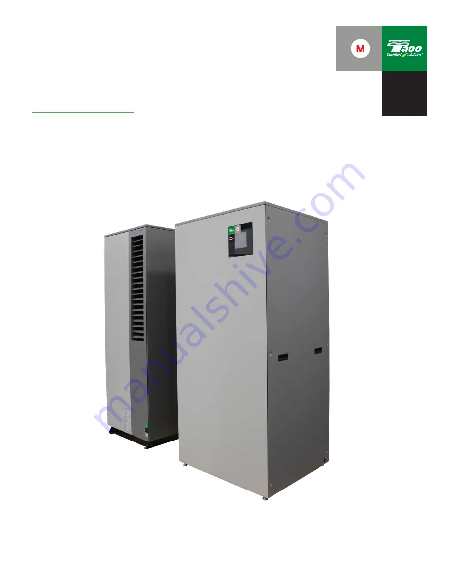
System M
Air-to-Water Heat Pump Outdoor Unit
HydroBox Building & User Interface Indoor Unit
Installation and
Operating Instructions
Document #: 802-001Plant #: 001-5040
Effective Date: July 15, 2022
Powered By
Glen
Dimplex
Page 1: ... M Air to Water Heat Pump Outdoor Unit HydroBox Building User Interface Indoor Unit Installation and Operating Instructions Document 802 001 Plant 001 5040 Effective Date July 15 2022 Powered By Glen Dimplex ...
Page 2: ... Side 6 4 Domestic Hot Water Connection 6 5 Temperature Sensor Connection 6 6 Electrical Connection 7 Touch Screen User Interface and App 7 1 Installing the GDTS Home App 7 2 Set up of the System M 7 3 Navigation of the User Interface UHI 8 AirPurging 9 Cleaning Maintenance 9 1 Maintenance 9 2 Cleaning Heat Pump 9 3 Cleaning the HydroBox 10 Faults Troubleshooting 3 4 5 6 7 8 21 23 23 23 11 Decommi...
Page 3: ... thus also intended for use by non professionals for heating shops offices and other similar working environments agricultural establishments and hotels guesthouses and other residential buildings The construction and design of the heat pump complies with all relevant EU and North American directives including DIN VDE UL FCC and CSA regulations When connecting the heat pump to the power supply the...
Page 4: ...orator cools the air i e extracts heat from it This extracted heat is then transferred to the working medium refrigerant in the evaporator The heat is pumped to a higher temperature level by increasing its pressure with the aid of the electrically driven compressors It is then transferred to the heating water via the liquefier heat exchanger Electrical energy is used to raise the temperature level...
Page 5: ...ressor 5 Liquefier 3 2 Chiller heat pump manager The chiller heat pump manager included in the scope of supply must be used to operate the reversible air water chiller heat pump The chiller heat pump manager is a convenient electronic reg ulation and control device It controls and monitors the entire heating system based on the outdoor temperature or room temperature as well as domestic hot water p...
Page 6: ...not be tilted more than 45 in any direction Caution Before commissioning the transport fastening must be removed www glendimplex de 452169 66 04 FD 0007 5 4 Transport 4 1 Monoblock A pallet should be used to transport the chiller heat pump to its final installation location The basic device can be transported with a lift truck hand truck or by means of 3 4 pipes fed through the holes in the basepl...
Page 7: ...connections can be accessed by removing the left side panel of the HydroBox Although all panels can be removed the HydroBox was designed to be able to access all serviceable components and access all wiring connections by just removing the side panels It must be possible to carry out maintenance work without hindrance This is ensured if the clearance displayed below is maintained The specified dim...
Page 8: ... condensate pipe laid in an area which is not frost free can destroy the evaporator 1 Supply Connection to HydroBox 1 1 4 NPT 2 Return Connection from HydroBox 1 1 4 NPT 3 Feedthrough for Condensate Hose 4 Feedthrough for Electrical Communications Lines 5 Optional Knockouts for Side Electrical Connections The supply and return piping between the heat pump and the HydroBox should be a minimum of 1 ...
Page 9: ... floor drain or other means of water collection dispersement as required by code A Taco 4900 Air Separator is internal to the piping and a Taco Hy Vent is connected at the top of the buffer tank Both provide secondary air elimination within the HydroBox Both vents are shipped closed and should not be relied upon for main purging of the distribution system Additional vents should be located at the ...
Page 10: ...10 Fig 12A System M Heating Cooling DHW Typical Application Mechancial Drawing ...
Page 11: ...11 Fig 13A System M Heating Cooling DHW Typical Application Electrical Drawing ...
Page 12: ...12 Fig 12B System M with Boiler Back Up Either Heat Pump Only or Boiler Only Central heating boiler back up not DHW Mechanical Drawing ...
Page 13: ...13 Fig 13B System M with Boiler Back Up Either Heat Pump Only or Boiler Only Central heating boiler back up not DHW Electrical Drawing ...
Page 14: ...14 Fig 12C System M with Boiler Back Up Either Heat Pump Only or Boiler Only Central heating DHW boiler back up Mechanical Drawing ...
Page 15: ...15 Fig 13C System M with Boiler Back Up Either Heat Pump Only or Boiler Only Central heating DHW boiler back up Electrical Drawing ...
Page 16: ...he DHW tank call always has priority Field wiring is required between the HydroBox indoor unit and the DHW tank sensor shipped with the System M see section 6 6 5 Separate 120v and 240v power connections and a field supplied contactor is also required to activate the SMT85 DHW tank and the immersion heater see section 6 6 1 A domestic hot water recirculation system can be used as part of the overa...
Page 17: ...ng Mount the outdoor sensor loosen the bottom nut then push the thermostat sensor wire through nut and the into each of the terminal blocks tighten them down with the screws Re tighten the nut Run the wiring back to the HydroBox wiring hub terminals numbers 4 and 5 The connections are not polarity sensitive so either wire can go to either terminal Outdoor Temperature and DHW Sensor Design Paramete...
Page 18: ...N ACCESSORY BAG WITH THE HEAT PUMP OUTDOOR UNIT CLIP ON FERRITE PART F60 02 TO BE FIELD INSTALLED WITH ON LINE AND NEUTRAL E LEADS OF THE 120V POWER INPUT TO THE HEAT PUMP OUTDOOR UNIT INCLUDED IN ACCESSORY BAG WITH THE HEAT PUMP OUTDOOR UNIT G L1 L2 GND A B 1 2 1 2 1 2 1 2 1 2 DOMESTIC HOT WATER CIRCULATING PUMP M18 1 2 M18 X2 N0 L N PE L N GND J11 Rx T Rx T GND DI8 L N G L N G L G N Y2 N L N L 1...
Page 19: ...r Unit Indoor Unit Indirect Water Heater w 4 5kW Electrical Back up Immersion Heater Electrical Disconnects per code 240 1 60 L1 L2 PE L1 L2 PE 240 1 60 L1 L2 PE L1 L2 PE 240 1 60 L1 L2 PE L1 L2 PE Optional M13 Heating Cooling Circuit Pump 0 10VDC 15 Amp Circuit Breaker 35 Amp 2 Pole Circuit Breaker 30 Amp 2 Pole Circuit Breaker 30 Amp 2 Pole Circuit Breaker Ethernet Cable Power to Back up Electri...
Page 20: ... UNIT TERMINAL N0 J11 B 1 2 1 2 1 2 1 2 1 2 N L N L 8 AWG GND GND GND GND L1 L2 OUTDOOR TEMPERATURE SENSOR DHW TEMPERATURE SENSOR HEATING DEMAND SMART GRID 2 FORCED COOLING CHANGE OVER HEAT COOL CIRC PUMP 0 10 VDC SIGNAL POWER OUTPUT CONTACTOR FOR DHW IMMERSION HEATER 120 VAC 1A POWER INPUT 120 VAC 5A GROUND BUFFER TANK IMMERSION HEATER 240 VAC 26A 710 1048 GND A COMMUNICATION TO HEAT PUMP OUTDOOR...
Page 21: ...tween an external router A350 and the LAN plug on the back panel of the HydroBox indoor unit See section 11 The heat pump circulating pump M16 and domestic hot water tank circulating pump M18 are powered with 120v and designed to be operated in variable speed mode controlled through a 0 10 VDC signal Both circulator pumps are Taco 0034e SF A temperature sensor is installed in the return line befor...
Page 22: ...Screen Reference Name LOCK1 Lock Screen Clock The default display is a clock showing the date and current outdoor temperature Touch anywhere on the screen to begin If the user interface is left idle for more than 5 minutes it will return to this screen time is adjustable in SETTINGS LS screen LOGIN1 Login Screen Drawn a M pattern starting from the bottom left dot to access the general menu and set...
Page 23: ...ow is maintained To ensure proper drainage from the condensate tray it must be regularly inspected and cleaned if necessary To prevent faults due to sediment in the heat exchangers care must be taken to ensure that no impurities can enter either the heat source system or the heating system In the event that operating malfunctions due to contamination occur nevertheless the system should be cleaned...
Page 24: ...44 in F m h Pa gal min psig 1 40 10 600 6 16 1 54 3 4 Sound level according to EN 12102 with A7 W55 in C A45 W131 in F outdoors Normal operation reduced operation 7 dB A 59 57 3 5 Sound level at a distance of 10 m outdoors 8 Normal operation reduced operation 7 dB A 29 27 3 6 Air flow Normal operation reduced operation 7 dB A 3 800 3 000 2 237 1 766 4 Dimensions weight and filling quantity 4 1 Dev...
Page 25: ... metals powder like substances or chemicals e g in the nearness of livestock breeding hot springs etc 2 For air temperatures between 22 C 7 F and 5 C 23 F flow temperature increasing from 45 C 113 F to 60 C 140 F 3 For details see performance curves General tolerance for heating or cooling capacity power consumption coefficient of performance 10 General tolerance for temperature conditions 2K 4 By...
Page 26: ...es Hatched area footprint heatpump 55 2 2 70 2 7 110 4 3 1 2 3 4 1 2 Drain pipe P 50 mm flush with foundation 97 3 8 60 2 4 Condensate hose 3 854 33 6 542 21 3 71 2 8 5 13 2 Dimension Drawing Legend 1 Supply Connection to HydroBox 1 1 4 NPT 2 Return Connection from HydroBox 1 1 4 NPT 3 Feedthrough for Condensate Hose 4 Feedthrough for Electrical Communications Lines 5 Optional Knockouts for Side E...
Page 27: ...O RETURN THE DOCUMENT TOGETHER WITH ALL COPIES MADE IMMEDIATELY WHEN REQUESTED BY TACO APP QA INCHES MM 07 16 2020 aco Inc 4 4 OF SHEET JJK UNLESS OTHERWISE SPECIFIED ANGLES 1 FEATURE CONTROL SYMBOLS PER ANSI Y14 5 R 005 127 TO 015 38 BREAK SHARP EDGES 125 FINISHES FRACTIONS 1 64 397 XX 02 508 XXX 005 127 XXXX 0005 0127 ECO Submittal SCALE 1 4 CI VOL DATE APP ENG APP MFG DR BY PRELIMINARY REV D 1 ...
Page 28: ...978 34 5 876 33 5 851 10 5 267 29 38 746 59 94 1522 61 44 1561 63 38 1610 ø 28 711 4 102 4 102 8 203 SENSOR WELL 3 4 MNPT FITTING COLD WATER SUPPLY 3 4 MNPT FITTING HOT WATER SUPPLY T P VALVE 4 X4 JUNCTION BOX STEEL ELECTRICAL ENCLOSURE IMMERSION HEATER ANODE DRAIN 1 1 2 MNPT HEAT PUMP SUPPLY RETURN ...
Page 29: ... 24000 0 0 0 5 1 0 1 5 2 0 m h Pa pressure drop psig monobloc max min 50 60 70 80 90 100 110 120 130 140 10 15 20 25 30 35 40 45 50 55 60 65 25 20 15 10 5 0 5 10 15 20 25 30 35 40 C C heating water outlet temperature F Water outlet 2 K min Water Inlet 2K 0K The maximum Flowtemperatures are reached by compliance with the minimum heaƟng water Ňow operaƟng envelope 13 8 3 2 7 12 17 22 27 32 37 42 47 ...
Page 30: ...he shown operating envelope General tolerances 10 0 000 1 000 2 000 3 000 4 000 5 000 6 000 7 000 8 000 9 000 10 000 11 000 12 000 13 000 14 000 15 000 16 000 17 000 0 1 2 3 4 5 kW electrical power consumption BTU h The min and max curve describes the range of the power consumption within the shown operating envelope General tolerances 10 0 1 2 3 0 4000 8000 12000 16000 20000 24000 0 0 0 5 1 0 1 5...
Page 31: ...tenance so that this can be performed as effectively as possible The data is encrypted on all transmission paths using state of the art encryption methods Personal data required for maintenance purposes such as your address contact details and framework data on the contract is made available to after sales service partners so that they can carry out maintenance and repair services The control and ...
Page 32: ...ntenna s used for this transmitter must be installed such that a minimum separation distance of 20cm is maintained between the radiator antenna and all persons at all times and must not be co located or operating in conjunction with any other antenna or transmitter Taco Inc Taco or the Company will repair or replace without charge at the Company s option any Taco product or part which is proven de...