


3
3
On
Off
1
2
3
8
4
5
6
7
9
10
RANGE
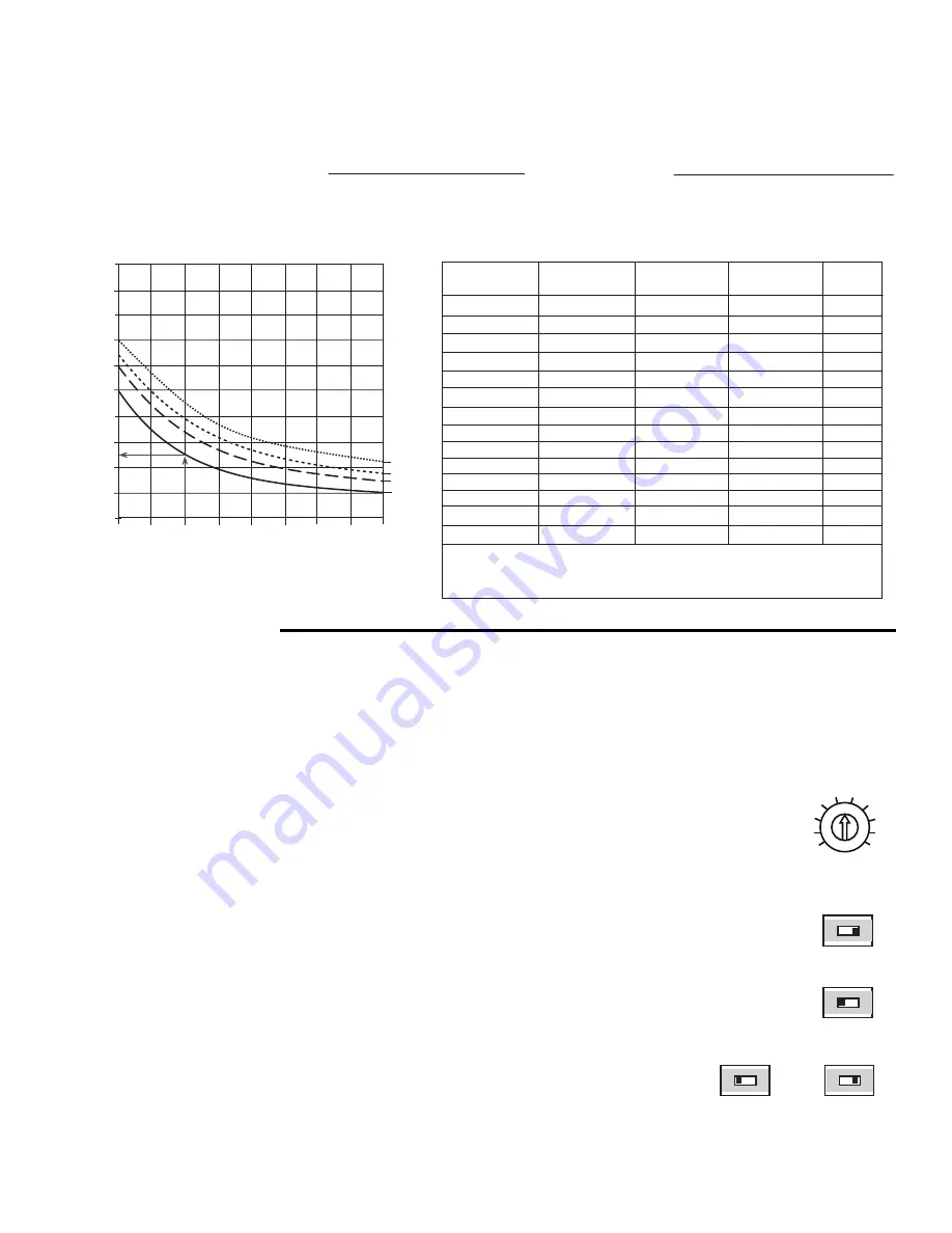
Design Injection Flow Rate (US GPM) = System Flow Rate (US GPM) x Flow Ratio
Eq. 3:
Eq. 1:
System Flow Rate (US GPM) =
500 x
∆
Ts (°F)
Design Heating Load (BTU/hr)
Eq. 2:
∆
Ts (°F) =
500 x System Flow Rate (US GPM)
Design Heating Load (BTU/hr)
Tb - Ts (
°
F)
∆
Ts (
°
F)
0.40
0.00
0.20
1.00
0.80
0.60
10
30
50
70
90
Fig. 2
10
15
20
25
Flow Ratio
20
40
60
80
0.10
0.30
0.50
0.70
Fig. 3
Nominal Pipe
Diameter (inches)
TACO
Pump
This table assumes there are 5 feet of pipe, 4 elbows, and 4 branch tees of the listed diameter.
Balancing valve is assumed to be a ball valve. The approximate Cv value is provided in order
to allow for proper balancing device. Valve characteristics may vary for the same size and type
of ball valve from manufacturer to manufacturer.
Balancing
Valve Cv
Balancing Valve
Position (% open)
Design Injection
Flow Rate (US GPM)
20
30
25
40
40
2
0012
0012
0010
0010
0010
0010
007
007
007
007
006
2
1
1
1
1.5
1
0.75
0.75
0.5
1.25
34.2
18.2
28.8
19.8
10.8
10.8
10.4
6.9
15
5.76
36
30
50
50
100
50
40
40
40
100
30
16
14
12
9
7
8
4
003
0.5
2.4
30
1.5
2
003
0.5
4.5
40
3
006
0.5
4.5
40
0.90
5) Decide whether or not to include a balancing valve in the injection piping. A balancing valve allows adjustment when the injection
pump is larger than needed. A balancing valve also provides the possibility of manual operation of the system by turning the injec-
tion pump fully on and adjusting the balancing valve to obtain the desired supply water temperature.
6) The injection pump size and model of Taco 00 pump to install can be looked up in figure 3. Do not oversize the injection system. If
the injection system is not able to provide enough heat, the boiler’s aquastat may be increased.
Sequence of Operation
Power up and Heat Request
Whenever the 00-VS is powered up, the green PWR LED turns on. The 00-VS starts operating once a heat request signal is present
at the Heat Request (Ht Req) terminals. A heat request signal may be provided by external end switches from zone valves or ZVC/SR
series zone controls, applying a dry contact closure or a powered 24 V (ac) signal across the Ht Req terminals. If end switches or
switching relays are not available, a jumper must be installed to provide a heat request. Once a heat request signal is present, the
green HEAT REQ LED turns on.
Mixing Operation
Once a heat request is present, the 00-VS operates to maintain a target temperature based on either a fixed
setpoint or a fixed temperature difference (
∆
T). The percent output (% OUT) LED flashes at different rates based
on the speed of the pump. The target temperature is set using the RANGE dial, where the numbers on the dial
correspond to the temperature ranges available in the applicable mode. Refer to the Setpoint and
∆
T sections
for a listing of the temperature ranges available.
The operation of the 00-VS is based on either direct acting or reverse acting operation.
Direct Acting (DIP switch 3 = Off)
In direct acting operation, the 00-VS increases speed on a temperature decrease and decreases speed on a
temperature increase. Direct acting operation is typically used in heating applications.
Reverse Acting (DIP switch 3 = On)
In reverse acting operation, the 00-VS increases speed on a temperature increase and decreases speed on a
temperature decrease. Reverse acting operation is typically used in cooling applications.
3
On
Off
Fast
Response
4
On
Off
Normal
Response
4
On
Off
Variable Speed Output Response
The 00-VS allows for adjustment to the response rate. The response rate is the speed at which
the 00-VS operates to achieve target temperature. The response adjustment is made through DIP
switch 4.
The normal response is typically used in applications where the temperature at the sensor being
controlled changes gradually during operation.
The fast response is typically used in applications where the temperature at the sensor being con-
trolled changes rapidly during operation.


