T-Line MINI ID Operation Manual Download Page 5


Manual Part Number:


5-06-4900-74-0


Manual File:


023524 Rev. A


P a g e

 | 

V


General Cautions


ALWAYS

  wear  eye  and  skin  protection  when  working  with  refrigerants.    Escaping 

refrigerant vapors will present a freezing danger.


ALWAYS

  turn  the  compressor 

OFF

  before  connecting  the  instrument  to  an  air 

conditioning system.


ALWAYS

  inspect  the  sample  hose  before  each  use.    Replace  the  hose  if  it  appears 

cracked, frayed, obstructed or fouled with oil.


DO NOT

 direct refrigerant vapors venting from hoses towards the skin.


CAUTION

  –  Do  not  pressure  test  or  leak  test  HFC-134a  service  equipment  and/or 

vehicle air conditioning systems with compressed air.  Some mix-tures of air and HFC-
134a have been shown  to be combustible at elevated pressures.  These mixtures,  if 
ignited, may cause injury or property damage. Additional health and safety information 
may be obtained from refrigerant manufacturers.


DO NOT

 disassemble the instrument.  There are no serviceable components internal to 

the instrument and disassembly will void the warranty.


ALWAYS 

place the Analyzer on a flat and sturdy surface.


To reduce the risk of electrical shock, do not disassemble the instrument; do not use the 
instrument in wet or damp areas.


AVOID

 breathing A/C refrigerant and lubricant vapor or mist.  Exposure may irritate eyes, nose 

and throat.  To remove HFC-134a from the A/C system, use service equipment certified to meet 
the requirements of SAE J2788. Additional health and safety information may be obtained from 
refrigerant and lubricant manufacturers.


DO NOT

 utilize any hose assembly other than those supplied with the instrument.  The 

use of other hose types will introduce errors into the refrigerant analysis and instrument 
calibration.


ALWAYS

 verify that the refrigerant which is tested from the Low Side does not contain 

or will not emit heavy loads of oil or liquid.


CAUTION 

– Should be operated by certified personnel.


NEVER

 admit any sample into the instrument at pressures in excess of 

300 psig


NEVER

  obstruct  the  air  intake,  sample  exhaust  or  case  ventilation  ports  of  the 

instrument during use.


WARNING

 – This Identifier must not be operated in flammable atmospheres.


Summary of Contents for MINI ID

Page 1: ...on PA 19341 USA Phone 610 524 8800 Fax 610 524 8807 Email info refrigerantid com www refrigerantid com T LINE MINI ID R134a REFRIGERANT ANALYZER OPERATION MANUAL Manual Part Number 5 06 4900 74 0 Manu...

Page 2: ...Manual Part Number 5 06 4900 74 0 Manual File 023524 Rev A P a g e II...

Page 3: ...ELCOME VII 1 INTRODUCTION AND OVERVIEW 07 2 PRODUCT DESCRIPTION 07 1 1 GENERAL 07 3 PRODUCT COMPONENTS 07 2 1 BASE MODULE 08 2 2 COUPLER WITH FILTER 08 2 3 CALIBRATION BULB 09 2 4 BATTERY CLIPS 09 4 I...

Page 4: ...mination Replace the brass oil filter of the instrument AS SOON AS OIL IS DETECTED IN THE SAMPLE HOSE Failure to properly maintain and replace the oil filter may result in severe damage SAMPLE INPUT W...

Page 5: ...instrument and disassembly will void the warranty ALWAYS place the Analyzer on a flat and sturdy surface To reduce the risk of electrical shock do not disassemble the instrument do not use the instrum...

Page 6: ...rmation regarding the application operation or spare parts please contact the Neutronics Inc Customer Service Department If you have questions or comments we would like to hear from you Neutronics Inc...

Page 7: ...ocarbons and air Refrigerant purity is automatically determined for refrigerant R134a by the instrument to eliminate human error The instrument is supplied complete with a R134a sample hose a 12 VDC p...

Page 8: ...Manual Part Number 5 06 4900 74 0 Manual File 023524 Rev A P a g e 8 3PRODUCT COMPONENTS 3 1 Base Module TEXT 3 2 Coupler with Filter TEXT...

Page 9: ...i ID It is a simple process requiring the operator to take these 4 steps 1 Connect the Low Pressure Vapor Sampling Hose to the Low Side Vapor port of the system or cylinder 2 Open the low side valve o...

Page 10: ...ehicles low side service port and then press NEXT 8 The Analyzing light will illuminate for approximately 45 seconds while the test is in progress 9 The PASS FAIL light will then provide the test resu...

Page 11: ...ary Remove any oil in the coupler with compressed air and a dry cloth Replacement Filter P N 6 01 6001 23 1 The Mini ID is equipped with internal fault codes for assistance with troubleshooting When t...

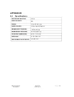
Page 12: ...FRIGERANT DETECTED R 134a PASS FAIL PURITY 95 POWER 12 15 VDC 1 amp SAMPLE SOURCE Oil Free Vapour Refrigerant MINIMUM INPUT PRESSURE 1 38 Bar 20 Psig MAXIMUM INPUT PRESSURE 20 70 Bar 300 Psig OPERATIN...

Page 13: ...m and against all losses and claims to or by any person or property caused in any manner by the goods or the use of the goods including any expenses and attorney s fees in connection with all claims d...

Page 14: ...PARAGRAPH NEUTRONICS INC MAKES NO WARRANTIES EXPRESSED OR IMPLIED INCLUDING WARRANTIES AS TO MERCHANTABILITY OR AS TO THE FITNESS OF THE GOODS FOR ANY PARTICULAR USE OR PURPOSE AND ANY WARRANTIES SET...

Reviews: