SyxthSense Ltd
Copyright © 2009 SyxthSense Ltd. All rights reserved - 03/2009
PS
SN1.125
- 2/5
Online store:
www.syxthsense.com
Enquiries: T:
0870 20 80 100
F:
0870 20 80 200
RY-FL Communication
As the communication is bi-directional all the time, is also the transmitter aware of the function of the
network. The wireless devices are able to inform about the problems in the network and about the
needed service to the FLTA network masters. For example the RY-FL is alarming when the signal has
been lost over an hour, and the device turns its outputs off. Output voltage is set 0 V and PWM is 0 V.
RY-FL Network / Wireless
System Overview
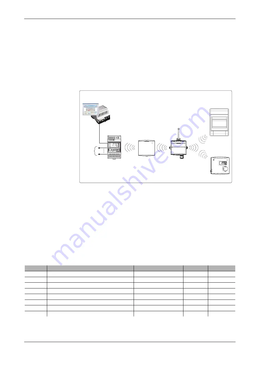
The diagram below illustrates the typical wireless network when RY-FL input / output devices are used
in the system. RY-FL I/O-modules is continuously communicating over the wireless network to the
FLTA master (version 2.2 or later) and the FLTA is sending the output commands to the RY-FL
input/ouput module.
When FLTA receivers are used with any wireless sensor or transmitter (e.g. TEFL, TEU-FL, LA-FL
and KLU-FL), each FLTA network can have up to 99 sensors/transmitters and up to 8 FL-REP
repeaters/signal boosters. In the RY-FL network due to extended network messaging the maximum
number of FL-REP repeaters is limited to 2 and the maximum number of RY-FL input / output modules
to 20 per network. The system can still have up to 99 sensors / transmitters (including RY-FL
input/ouput modules) as a part of the solution.
MAXIMUM WIRELESS SYSTEM SIZE PER NETWORK (WITH RY-FL I/O MODULES)
Maximum number of FLTA networks is 63. Therefore in a larger installation it is possible to have
maxiumum of 20 x 63 = 1,260 RY-FL wireless I/O modules.
NOTE:
RY-FL requires FLTA version 2.2 or later and FLSER service tool version 2.2 or later.
RY-FL Modbus
Communication
The RY-FL wireless input/output modules communicate via 868 Mhz radio signal to the FLTA network
master. A FLTA network master has 8 x 0..10Vdc outputs that can be used to represent the RY-FL
measurements. The FLTA network masters have also built-in Modbus RTU communication that
provides the intelligent interface to read the wireless measurements and to control the RY-FL output
signals.
Example. The table below illustrates typical Modbus parameters available via FLTA for RY-FL with
device address 1 (RY-FL address set to 1 a t the commissioning).
Note: If Digital Output register is enabled (ON), then the corresponding channel analogue output is
disabled (it is only possible use digital output or analogue output on a RY-FL channel, not both).
For full listing of the available FLTA Modbus commands please consult the FLTA Modbus
Communication User Guide.
No. of Devices
Up to 99 (including TEFL, KLU-FL, TEU-FL and LA-FL)
No of RY-FL Modules
Max. 20
No. of Repelaters
Max 2 when RY-FL modules are used (otherwise 8)
M
14
13
12
11
10
9
8
7
6
5
4
3
2
1
FLTA v.2.2
Radio Signal
868.30 MHz
Up to 63 FLTA
Master Modules
Range (between 2 wireless devices):
In buildings: 20..100m
(depending wall structures)
Line of sight: Up to 500m
RY-FL WIRELESS IO-MODULE
WITH MODBUS RTU CONNECTION VIA FLTA
EXAMPLE NETWORK
A1 to A8
0..10Vdc
Analogue
Outputs
Modbus RS-485
Communication
MODBUS Master
Device
FLREP
Optional up to 2 Repeaters
(FLREP or FLREP-U)
per FLTA/RY-FL network
M
16
FLREP-U
A
0
1
2
3
TEFL
RY-FL
Up to 20 RY-FL
Input / Output Modules
Up to 99 TEFL, TEU-FL, KLU-FL
and LA-FL Sensors / Transmitters
(max. 99 including RY-FLs)
RY-FL Inputs / Outputs
2 Digital Inputs / 2 Analogue Inputs
2 0..10Vdc Outputs / 2 Relay Outputs
(individually configurable, total 4 IOs)
Register
Parameter Description
Modbus Function Code
Data Type
Range
10
301
Device 1 Digital Input 1 (DI1) Status
02 - Read Discrete Inputs
Bit
On - Off
10
401
Device 1 Digital Input 2 (DI2) Status
02 - Read Discrete Inputs
Bit
On - Off
30
248
Device 1 Analogue Input 1
04 - Read Input Registers
Signed 16
0..100%
30
249
Device 1 Analogue Input 2
04 - Read Input Registers
Signed 16
0..100%
1
Device 1 Digital Output 1 (DO1) - See Note
05 - Write Single Coil
Bit0
On - Off
2
Device 1 Digital Output 2 (DO2) - See Note
05 - Write Single Coil
Bit1
On - Off
400
50
Device 1 Analogue Output 1 (AO1) - See Note
06 - Write Holding Registers
Signed 16
0..100%
400
51
Device 1 Analogue Output 2 (AO2) - See Note
06 - Write Holding Registers
Signed 16
0..100%


