SYStronics TIC-4M User Manual Download Page 20

TIC-4M MANUAL

20

Electronic control equipment has different operating characteristics from electromechanical equipment. Safety 
instructions for the application, installation and maintenance of the electronic control unit, important differences 
between the electrical and electronic control unit and the electric machine, and contents of the use for the 
electric control unit. Due to these differences and the various uses of electronic equipment, the person 
responsible for the application of this equipment must use and install this equipment only within the permitted 
scope of application.

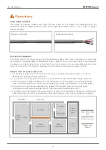
Overview of electrical noise control

Electrical noise can be caused by normal operation of components or components of the system due to
voltage spikes. The conduction mechanism may interfere with the operation of parts or elements of other
systems (noise interference), resulting in malfunction.

Generate noise source

1. Mechanically switched inductive loads generate strong noise intermittently. (MC, MCCB, etc.)
2. PWM drive power output generates severe continuous noise.
3. Switch mode DC power supply (SMPS) may continue to generate noise.
4. Noise source may occur due to contact switching.

Among the causes of the above noise sources, the noise that the system manufacturer can reduce is only
the contact switching noise.

Conduction noise

Electrical noise interferes with the normal operation of the equipment. In the case of electrical noise 
conduction, noise may be directly conducted by the system power wiring, and may be emitted to the outside 
through the wiring of the industrial control device (inverter).

ACㆍDC power cable installation

For AC·DC power installation, it is recommended to use junction, isolation, shielding and filter for power 
supply and related wiring.

Motor power cable installation

If possible, do not extend the motor power cable. In principle, the cable between the drive and the motor can 
not be used in extended connection. The universal reason for changing (extending) cables in the middle is 
for applications that require flexible cables. Observe the following guidelines when handling the remaining 
cables.

1. Do not detect different types of cables together. A transformer which is valid in HF is formed.
2. Cable length should be cut to fit the application.
3. If you can not cut the remaining cable, please arrange it in '8' or 'S' form. Never roll it round.
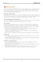
Precautions

Good example

Good example

Incorrect example

Summary of Contents for TIC-4M

Page 1: ...301 Bucheon Techno park 345 Seokcheon ro Bucheon si Gyeonggi do Republic of Korea Phone 10 32 324 2777 Fax 10 32 324 2717 Homepage www ss22 com TIC 4M USER MANUAL Compact Temperature Controller VER 1...

Page 2: ...nlight 4 Places affected by electromagnetic waves 5 Places where high temperature or humidity is high sites with over 85 of ambient humidity 6 Places where dust and salt are plentiful Precautions on i...

Page 3: ...o input 2 ports by setting the temperature monitoring port according to the setting conditions and customize it to suit the site conditions This is a product that is equipped with a built in communica...

Page 4: ...ent Controller 1EA TIC 4M Bracket 2EA Normal type NTC sensor 1EA SCTS 01 Sensor Component Advanced NTC sensor 1EA SCTS 02 High temperature type NTC sensor 1EA SCTS 03 Well type NTC sensor 1EA SCTS 04...

Page 5: ...A Relay output Output Port 4 Port Input power output Input Port 2 Port Non power source Changeable to temperature sensor input Sensor Port 1 Port NTC 10K at 25 1 Communication Port 1 Port RS 485 Opera...

Page 6: ...Advanced type cable sensor SCTS 02 Temperature Range 45 105 NTC 10K at 25 0 5 Sensor Weight 37 5g Cable 3M standard High temperature type cable sensor SCTS 03 Temperature Range 45 150 NTC 10K at 25 1...

Page 7: ...TIC 4M MANUAL 7 Front view Product Dimension Top view Side view Front view Side view Bracket Dimension Controller Dimension Display 42 5 x 20 3...

Page 8: ...mm x 30 mm in accordance with the specification insert the controller into the perforated holes 2 Push the controller onto the wall and secure it firmly by pushing the bracket When disconnecting remov...

Page 9: ...duct Wiring Diagram L L Sensor INPUT COM DI1 DI2 DO1 DO2 DO3 DO4 220VAC Relay 220VAC 5A COMP FAN DEF AL circuit breaker R N 220VAC Set output function DO3 DO4 Input function input contact setting poss...

Page 10: ...up screen Alarm generated for 2 seconds by pressing for 2 seconds DEF UP key Defrost ON OFF Detailed menu movement and increased menu data value PWR DOWN key Controller power ON OFF Detailed menu move...

Page 11: ...t the current temperature of 20 or below Heating Deviation OFF 0 1 9 9 OFF The function of setting up the heater while operating the controller while operating the controller OFF Without auxiliary hea...

Page 12: ...eter Set Main Display Cooling Delay After Defrosting Fan Delay after Defrosting Defrosting Time Defrost Cycle Defrost Mode Defrost Set High Temp Alarm Heater Alarm Comp Alarm Alarm Set Comp Integratio...

Page 13: ...e Comp output is turned ON and OFF Fan Mode ON Au ON Set the air flow mode ON The fan output is ON whenever the controller is in operation Auto flower is driven in conjunction with the Compton output...

Page 14: ...rature an alarm is generated If the temperature is 1 degree below the set point of the high temperature alarm the alarm is cleared Heater operation stops when high temperature alarm occurs OFF Alarm i...

Page 15: ...een Input Contact 1 Input 2 Set Input 1 Set Output 4 Set Output 3 Set System Set Comp Alarm Return Alarm Set Temp Filtering Temp Display Interval Display Set Input Contact 2 Temp Sensor Calibration Lo...

Page 16: ...ct method of the port n o Operates normally when the corresponding input is detected n C Normal operation should be performed if no corresponding input is detected during operation Alarm Setting Categ...

Page 17: ...of the operation alarm Normal operation High Temp Alarm Alarm occurs when control temperature is higher than high temperature alarm during controller operation Heating operation stops when an alarm oc...

Page 18: ...Reset Push for more the 2sec Notice All settings on the controller will return to their initial state Push for more the 10sec Main Screen Factory Reset Menu Factory Reset Complete Factory Reset Cance...

Page 19: ...he precautions and instructions specified in the manual For more information on the service refer to the product warranty statement in the user manual 1 Please note that any problem failure caused by...

Page 20: ...o generate noise 4 Noise source may occur due to contact switching Among the causes of the above noise sources the noise that the system manufacturer can reduce is only the contact switching noise Con...

Page 21: ...to install close to the line where the noise is generated and the line where the noise is generated by placing a plated steel barrier 2 If you need a lot of noisy power in area A it is recommended to...

Page 22: ...il s positive or negative terminal or an equivalent snubber capacitor Generally 100 and 0 1Uf are connected in series but it needs to be adjusted according to the load power How to Identify the Source...

Page 23: ...TIC 4M MANUAL 23...

Reviews: