Systematics, Inc. West Chester, PA. 19380
5
FITTING AND THREADING THE ELECTRODE
WIRE - ALWAYS USE ER70S-6 WELDING
WIRE WHEN WELDING STEEL.
1. Remove the wire spool clip from
the spool hub.
2. Unpack the spool of welding wire
from its protective packaging.
3. Place the spool of ER70S-6 weld-
ing wire onto the hub. The wire
is fed off the bottom of the
spool.
CAUTION
Look for wire protruding
from the center of the
spool. The protruding wire
is electrically HOT during
welding and must not touch
the machine. Cut this wire
flush with the spool.
4. Replace the spool clip on the
hub.
5. Unlatch the pressure roll arm
and swing it open.
6. Make sure the double v-groove
drive roll is installed to match
the wire size. To change the
wire size setting, remove the
drive roll, turn it over and
reinstall it on the shaft.
(continued on following page)
"B" SIDE FACING IN FOR
.023" - .035" STEEL WIRES
"C" SIDE FACING IN FOR
.040" - .045" STEEL WIRES
AND 3/64" ALUMINUM WIRES
5. Check that the gas regulator is
properly adjusted. When welding
steel, the gas flow rate is 30
CFH. When welding aluminum, the
gas flow rate is 40 CFH.
NOTE
The PBE180 must be turned
"ON" and the MIG torch
trigger depressed, before
the gas flow rate can be
adjusted.
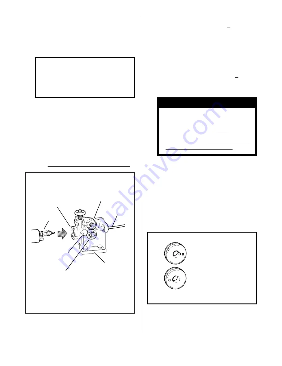
TORCH CONNECTION
1. Open the access door of the
machine to its fullest extent.
2. Back out the thumb screw located
on the drive assembly mounting
bracket inside the machine. In-
sert the MIG torch into the torch
panel mount on the front panel
and
TIGHTEN THE THUMB SCREW.
SHIELDING GAS CONNECTIONS (Cont.)
DRIVE
ASSEMBLY
MOUNTING
BRACKET
DRIVE
ROLL
TORCH
PANEL
MOUNT
THUMB
SCREW
PRESSURE
ROLLS
MIG
TORCH
INLET
GUIDE
FIG. 7. TORCH CONNECTION
FIG. 8. DOUBLE GROOVE DRIVE ROLL


