Installation |
11
4.3.1
Installation procedure
1
1 Prepare the surface where the unit is to be mounted.
Make sure that the surface is flat, levelled and that it sup-
ports the weight of the unit. Perform the installation in
accordance with local rules and regulations.
2
2 Lift the unit in place.
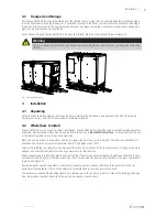
Warning
Beware of sharp edges during mounting and
maintenance. Make sure that a proper lifting
device is used. Use protective clothing.
3
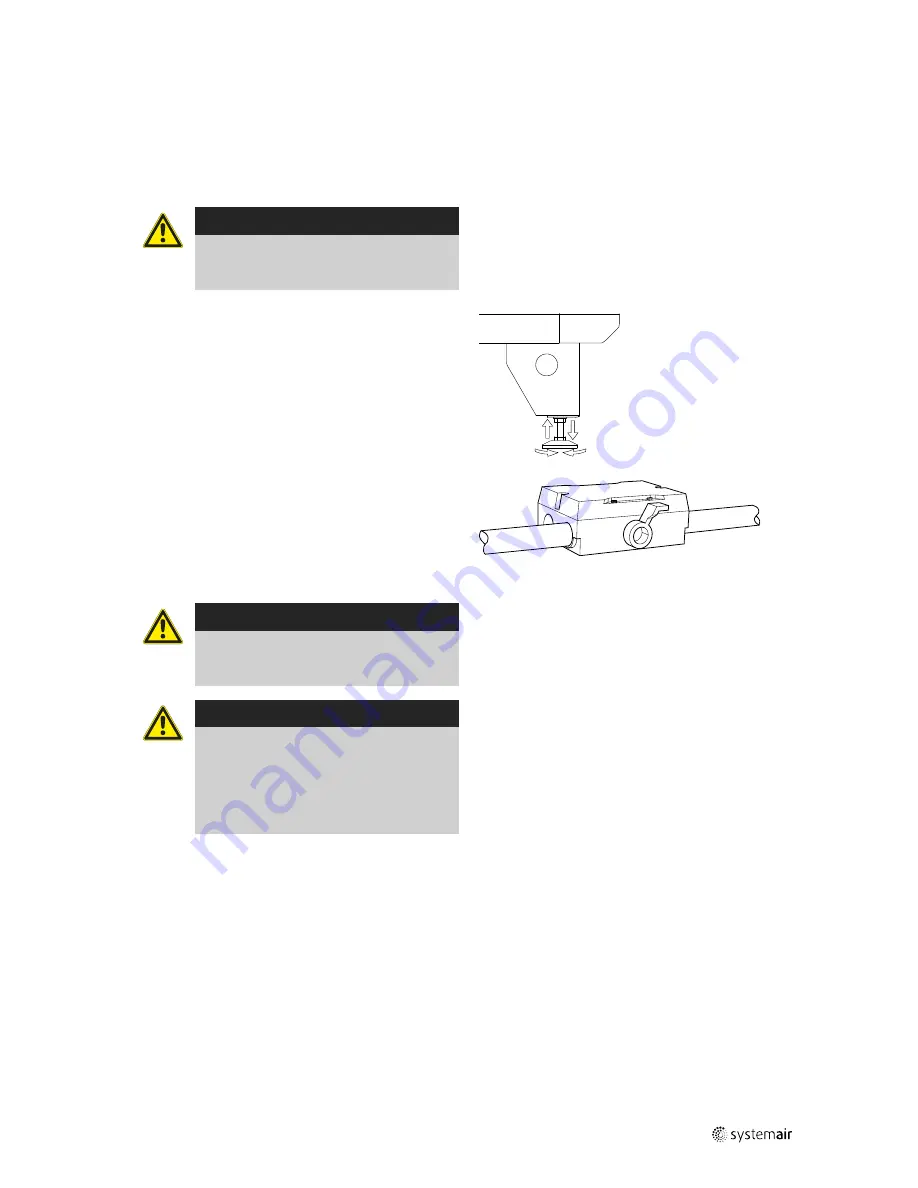
3 Level the unit with help of the enclosed mounting feet
4
4 Connect the unit electrically to the mains through the all
pole circuit breaker (safety switch), which is enclosed in-
side the unit on delivery. The wiring is led through the ga-
ble of the unit (Topvex SR 03-06) or through the top of
the unit casing (Topvex TR 03-06) directly to the electrical
connection box.
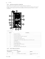
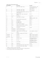
See enclosed wiring diagram, and below table (table 3)
for more information.
Warning
The units electrical connection to the mains
supply must be preceded by an all pole circuit
breaker with a minimum 3 mm gap.
Danger
• Make sure that the Mains supply to the unit
is disconnected before performing any
maintenance or electrical work!
• All electrical connections must be carried
out by an authorized installer and in
accordance with local rules and regulations.
4.4
Supply air sensor (Topvex SR 03-06)
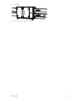
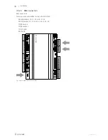
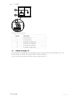
The supply air sensor is fitted in the duct after the unit in the supply air duct (figure 10). See table 3 to which terminals
the sensor needs to be connected in the electrical connection box. Other temperature sensors are built in to the unit
from factory. The supply air sensor is enclosed in the unit package on delivery.
124454 | A003
Summary of Contents for Topvex SR03
Page 4: ......
Page 16: ...12 Installation Fig 10 Installed supply air sensor right hand connected unit 124454 A003 ...
Page 25: ...124454 A003 ...
Page 26: ......
Page 27: ......


