background image

14

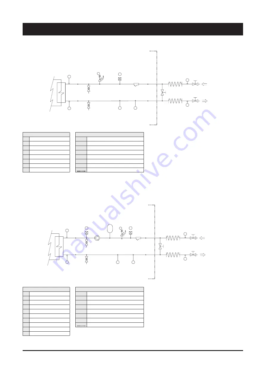
External water circuit - Basic Unit

4 - Installation

1

B

A

10

5

G

G

9

11

11

12

12

13

INLET

OUTLET

FS

I

8

E

D

8

COMPONENTS

1

Plate heat exchanger

5

Water filter

8

Pressure point/drain valve

9

Water outlet

10

Water inlet

11

Globe valve

12

Flexible pipes

13

By-pass valve

SAFETY/CONTROL DEVICES

A

Inlet water temperature sensor

B

Outlet water temperature sensor

D

Vent valve (105 mbar)

E

Water safety valve (3 bar)

FS

Flow switch

G

Thermometer

I

Hydrometer
Unit side

External water circuit - 1 Pump

8

D

2

E

8

I

FS

OUTLET

INLET

13

12

12

11

11

9

G

G

5

10

A

B

1

7

D

COMPONENTS

1

Plate heat exchanger

2

Pump

5

Water filter

7

Pressure expansion tank

8

Pressure point/drain valve

9

Water outlet

10

Water inlet

11

Globe valve

12

Flexible pipes

13

By-pass valve

SAFETY/CONTROL DEVICES

A

Inlet water temperature sensor

B

Outlet water temperature sensor

D

Vent valve (105 mbar)

E

Water safety valve (3 bar)

FS

Flow switch

G

Thermometer

I

Hydrometer
Unit side

Summary of Contents for SYSCROLL AIR CO/HP 40-75

Page 1: ...et de maintenance Installations und Wartungshandbuch Manuale di installazione e di manutenzione Manual de instalación y de mantenimiento SYSCROLL AIR CO HP 40 75 SYSCROLL AIR RE 40 75 ISO 9001 2008 certified management system 40 75 kW 40 75 kW Español Italiano Deutsch Français English Part number Code Code Codice Código 364354 F Supersedes Annule et remplace Annulliert und ersetzt Annulla e sostit...

Page 2: ......

Page 3: ... 6 SYSCROLL AIR CO HP CONTROL 6 1 Control of SyScroll Air CO HP Units 23 6 2 Keypad functions 23 24 6 3 Folder structure 24 6 4 Menù structure 24 6 5 Alarm list 25 7 SYSCROLL AIR RE CONTROL 7 1 Control system 26 7 2 Display 27 7 3 Keyboard 27 7 4 Alarms 28 8 PRODUCT DESCRIPTION 8 1 General information 29 8 2 Accessories 30 31 8 3 Refrigeration circuits 32 to 34 9 TECHNICAL DATA 9 1 Hydraulic featu...

Page 4: ... for this warranty to be valid the following conditions shall be met Q The machine must be operated only by skilled personnel from Authorised After Sales Service Q Maintenance must be performed only by skilled personnel from one of Authorised After Sales Centers Q Use only original spare parts Q Carry out all the planned maintenance provided for by this manual in a timely and proper way Failure to...

Page 5: ...y anomalous overpressure inside the plant Q The vents of the safety valves are positioned and oriented in such a way as to reduce the risk of contact with the operator in the event that the valve is operated Anyway the installer will convey the discharge of the valves far from the unit Q Dedicated guards removable panels with tools and danger signs indicate the presence of hot pipes or components ...

Page 6: ...ellery or any other accessory tat may be caught in moving parts Q wear suitable personal protective equipment gloves goggles etc when you have to work in the presence of free flames welding operations or with compressed air Q if the unit is placed in a closed room wear ear protection devices Q cut off connecting pipes drain them in order to balance the pressure to the atmospheric value before disc...

Page 7: ...ng sign do not turn on maintenance in progress on the external disconnecting switch Q make sure that on off remote controls are inhibited Q wear suitable personal protective equipment helmet safety gloves goggles and shoes etc To carry out any measurements or checks which require the activation of the machine Q work with the electrical board open only for the necessary time Q close the electrical ...

Page 8: ...ront column LAS BOMBAS MONTADAS EN ESTA UNIDAD NO PUEDEN TRABAJAR SIN AGUA DIE PUMPEN DIESES GERÄTES DÜRFEN NICHT OHNE WASSER BETRIEBEN WERDEN THE PUMPS ON BOARD OF THIS UNIT CAN NOT WORK WITHOUT WATER LES POMPES A BORD DE CETTE UNITE NE PEUVENT PAS FONCTIONNER SANS EAU LE POMPE ABORDO DI QUESTA UNITÀ NON POSSONO FUNZIONARE SENZA ACQUA Circuit drain Outside on the right hand front column USARE SOL...

Page 9: ...TTENTION Enlever l alimentation electrique avant d ouvrir Start up warning Outside the door of the electrical board ATTENZIONE INSERIRE LE RESISTENZE DI RISCALDAMENTO OLIO ALMENO 12 ORE PRIMA DI OGNI AVVIAMENTO SE PREVISTE PRIMA DELLA MESSA IN TENSIONE ASSICURARSI CHE LE VITI DEI CIRCUITI ELETTRICI SIANO SERRATE COMPLETAMENTE WARNING ENERGIZE THE CRANCKCASE HEATER FOR AT LEAST 12 HOURS BEFORE EACH...

Page 10: ...trations may result in the risk of asphyxia due to the reduction in the oxygen percentage in the atmosphere Remove the patient to fresh air and keep warm and at rest If necessary give oxygen In case of breathing difficulties or arrest proceed with artificial respiration In case of cardiac arrest proceed with cardiac massage Then obtain medical attention Recommendations Semiotics or support therapy...

Page 11: ...s and goggles or a mask Accidental release measures It is important to wear protective clothing and a respirator Stop the source of the leak if you can do this without danger Negligible leaks can be left evaporating under the sun providing that the room is well ventilated Considerable leaks ventilate the room Reduce the leak with sand earth or other absorbing substances Make sure that the liquid d...

Page 12: ...gles or a mask Wearing protective gloves is not mandatory but is recommended in case of prolonged exposure to refrigerant oil Accidental release measures It is important to wear protective clothing and especially goggles Stop the source of the leak Reduce the leak with absorbing substances sand sawdust or any other absorbing material available on the market Disposal The refrigerant oil and its was...

Page 13: ...pment even if it has provided for its organisation 3 2 Handling SyScroll units are designed to be lifted from above by means of cables and eyebolts A spacer shall be arranged between the cables in order to prevent them from damaging the unit see the figure aside Before handling the devices make sure the site you have chosen for the installation can withstand its weight and support its mechanical i...

Page 14: ...to prevent damage corrosion and or deterioration Q Make sure all openings such as for example water connections are well plugged and sealed Q Never store the units in a room where temperature is above 50 C R410A units or where the units are directly exposed to the sunlight Q Minimum storage temperature is 25 C Q It is recommended to leave the finned coils covered to protect them against any risk o...

Page 15: ...s Q The installation site shall be characterised by the presence of the space required for air circulation and for the performance of maintenance operations see chapter 9 for further details 4 2 External Water Circuit WARNING The external water circuit shall guarantee a constant water flow rate through the circulating refrigerant water heat exchanger evaporator under steady operating conditions an...

Page 16: ...alve 105 mbar E Water safety valve 3 bar FS Flow switch G Thermometer I Hydrometer Unit side External water circuit 1 Pump 8 D 2 E 8 I FS OUTLET INLET 13 12 12 11 11 9 G G 5 10 A B 1 7 D COMPONENTS 1 Plate heat exchanger 2 Pump 5 Water filter 7 Pressure expansion tank 8 Pressure point drain valve 9 Water outlet 10 Water inlet 11 Globe valve 12 Flexible pipes 13 By pass valve SAFETY CONTROL DEVICES...

Page 17: ...Vent valve 105 mbar E Water safety valve 3 bar FS Flow switch G Thermometer I Hydrometer Unit side External water circuit 1 Pump tank 2 8 D E 8 I FS OUTLET INLET 13 12 12 11 11 9 G G 5 10 A B 1 7 D 3 Y 4 11 11 COMPONENTS 1 Plate heat exchanger 2 Pump 3 Draining valve 4 Water buffer tank 5 Water filter 7 Pressure expansion tank 8 Pressure point drain valve 9 Water outlet 10 Water inlet 11 Globe val...

Page 18: ...lve 4 Water buffer tank 5 Water filter 6 Non return valve 7 Pressure expansion tank 8 Pressure point drain valve 9 Water outlet 10 Water inlet 11 Globe valve 12 Flexible pipes 13 By pass valve SAFETY CONTROL DEVICES A Inlet water temperature sensor B Outlet water temperature sensor D Vent valve 105 mbar E Water safety valve 3 bar FS Flow switch G Thermometer I Hydrometer Unit side Y Water drain ...

Page 19: ...e only for SyScroll Air HP units When heat pump units work in heating mode during defrosting cycles they may discharge water from the base This is why the units should be installed at least 200 mm above the floor level so as to allow the free drainage of waste water without the risk of producing ice banks The heat pump units must be installed in positions where the defrosting water cannot create a...

Page 20: ...supply circuit Q The electrical distribution system shall meet the power absorbed by the appliance Q The disconnecting and magnetothermal switches must be sized to control the starting current of the unit Q The power supply lines and the insulation devices must be designed in such a way that every line independent Q It is recommended to install differential switches to prevent any damage caused by...

Page 21: ...s manual and according to the wiring diagram which accompanies the unit WARNING Before connecting the power supply lines check that the available voltage value does not exceed the range specified in the Electric Data Chapter 9 For 3 phase systems check also that the unbalance between the phases does not exceed 2 To perform this check measure the differences between the voltage of each phase couple...

Page 22: ...20 SyScroll Air CO HP Version Electrical Connections 4 Installation ...

Page 23: ...21 English 4 Installation SyScroll Air RE Electrical Connections ...

Page 24: ... the pan must be approx 40 C and that the auxiliary control circuit is energised Q Check the operation of all the external equipment and make sure that the control devices of the plant are properly calibrated Q Start the pump and check that the water flow is correct Q Set the desired fluid temperature on the control board Q Start the appliance see Chapter 6 Q Check the correct direction of rotatio...

Page 25: ... card to connect the control to a BMS network remote display terminal wire remote control 6 1 Control of SyScroll Air CO HP units SyScroll Air CO HP units are provided with a microprocessor card fully programmed by default for the control of a heat pump unit General information The figure shows the terminal It is provided with a 4 red digits with 7 segments with decimal point led 18 LED and 4 butt...

Page 26: ...ey use 3 Password define visibility levels for parameters folders 4 Alarm log display alarm log Parameter folder gives access to following sub folders CL CE Cr CF configure device I O L local E expansion r remote F serial DQDORJXH LQSXWV W SH RI SUREH UDQJH GLIIHUHQWLDO ORJLF function GLJLWDO LQSXWV ORJLF IXQFWLRQ GLJLWDO RXWSXWV ORJLF IXQFWLRQ DQDORJXH RXWSXWV UDQJH VHULDO FRQILJXUDWLRQ FRPPXQLFD...

Page 27: ...n source side pump in case of condensing control option OFF M OFF Er45 Clock failure A Er46 Clock to be set A Er47 LAN communication error A Er48 Legionella set point not reached A Er60 RWT probe plant side failure OFF A OFF Er61 LWT probe plant side failure OFF A OFF Er62 Coil temperature probe failure OFF A Er66 Sanitary hot water probe failure OFF A Er67 Visualization probe T P failure A Er68 O...

Page 28: ...485 card to connect the Chiller Control to a BMS network remote display terminal wire remote control 7 1 Control system SyScroll Air RE units are provided with a microprocessor card which is fully programmed by default for the control of a condensing unit The control system consists of Keyboard Display Terminal General information The figure shows the terminal with the front door open It is provid...

Page 29: ...After you have selected the desired value press the ENTER key again to store it Access to the display mask of the machine status Esc key allows you to move from one mask to another Alarm key used to display the alarms to reset them in manual Press it one to display the mask of the activated alarm press it again to reset the alarm signal Prg Esc keys pressing these keys at the same time allows you ...

Page 30: ... Man No AL23a Thermal switch compressor 1 AUTO Reset Off Comp 1 On On Auto AL24 Thermal switch compressor 2 Off Comp 2 On On Man No AL24a Thermal switch compressor 2 AUTO Reset Off Comp 2 On On Auto AL27 Low pressure alarm Off On On Man Parameters AL27a Low pressure alarm AUTO Reset Off On On Auto AL29 Thermal switch fans Off Off On Man No AL29a Thermal switch fans AUTO Reset Off Off On Auto AL33 ...

Page 31: ...1 protection degree Compressors are powered on and off by the microprocessor of the unit control system which is intended to control the delivery of the thermal refrigerating capacity Evaporators Evaporators are made of stainless steel plates They are thermally insulated by means of a thick flexible insulating mattress with closed cells The maximum operating pressures correspond to 10 bar for the ...

Page 32: ...ressure with 2 pumps that guarantee 150 kPa of available static pressure Water buffer tank The hydro module is available for the units with a pump it is fitted inside and integrated in the circuit The module is entirely enclosed in a RAL 9001 galvanised and painted steel body The tank is covered with 10mm polyethylene insulation and it is provided with a 200W anti freezing heater On Off Remote kit...

Page 33: ... as accessory It is shipped loose and it s not possible to have it factory mounted Fan speed control Fan speed control is available as accessory to allow the chiller to operate down to external air temperature In Out valve kit In Out valve kit is available as accessory ...

Page 34: ...re Schrader valve SL 5 16 SAE low pressure Schrader valve H Thermometer Pipe connection with Schrader valve 1 4 SAE Probes Unit side Optional parts COMPONENTS VESSEL CATEGORY 2 EVALUATION MODULE 1 Compressor tandem scroll type 2 mod D1 2 Air cooled condenser 3 Filter drier 4 Sight glass 5 Thermostatic expansion valve 6 Plate heat exchanger 2 sizes 60 to 75 mod B D 7 Water inlet 8 Water outlet 9 In...

Page 35: ...r valve SL 5 16 SAE low pressure Schrader valve I Thermometer Pipe connection with Schrader valve 1 4 SAE Probes Unit side Optional parts COMPONENTS VESSEL CATEGORY 2 EVALUATION MODULE 1 Compressor tandem scroll type 2 mod D1 2 4 way valve 3 Air cooled condenser 4 Biflow filter drier 5 Sight glass 6 Biflow thermostatic expansion valve 7 Liquid receiver 2 mod D1 8 Suction accumulator 2 mod D1 9 Pla...

Page 36: ...ensor G Safety valve 45 bar 4 mod H1 M Discharge temperature sensor S 5 16 SAE Schrader valve charging point SH 5 16 SAE high pressure Schrader valve SL 5 16 SAE low pressure Schrader valve Pipe connection with Schrader valve 1 4 SAE Unit side Optional Probes COMPONENTS VESSEL CATEGORY 2 EVALUATION MODULE 1 Compressor tandem scroll type 2 mod D1 2 Air cooled condenser A G SH INLET OUTLET SL BT S D...

Page 37: ...0 13000 14000 15000 16000 17000 18000 60 75 50 40 45 Water flow l h Water flow l h Pressure drop kPa Pressure drop kPa 0 10 20 30 40 50 60 70 80 90 100 110 120 130 140 150 65 75 50 60 40 45 1000 1500 2000 2500 3000 3500 4000 4500 5000 Evaporator water pressure drop Desuperheater water pressure drop 9 1 Hydraulic features ...

Page 38: ...14000 14500 15000 15500 16000 16500 17000 17500 Water flow l h Available static pressure kPa Note The curves are referred to 2P T unit Unit without tank could have higher performance 0 8 3500 4000 4500 5000 5500 6000 6500 7000 7500 8000 8500 9000 9500 1000 10500 11000 11500 12000 12500 13000 13500 14000 14500 15000 15500 16000 16500 17000 17500 0 85 0 9 0 95 1 1 05 1 1 1 15 1 2 1 25 1 3 1 35 1 4 1...

Page 39: ...5 0 85 0 97 Pressure drop kPa 18 21 21 24 22 26 FANS Type Axial Number 1 1 1 1 1 1 Nominal speed rpm 680 680 680 900 900 900 Air flow rate m3 s 4 4 3 7 5 9 5 9 5 9 Power input kW 0 98 0 98 0 98 2 00 2 00 2 00 AIR COOLED CONDENSER Type Coil Number 1 1 1 1 1 1 Total coil face area per coil m2 2 6 2 6 2 6 3 2 3 2 3 2 Number of rows 2 2 3 3 3 3 HYDRAULIC CONNECTIONS EVAPORATOR Type Threaded gas male I...

Page 40: ...21 20 23 20 26 FANS Type Axial Number 1 1 1 1 1 1 Nominal speed rpm 530 530 530 720 720 720 Air flow rate m s 3 05 3 05 2 86 4 4 4 4 4 4 Power input kW 0 57 0 57 0 57 1 27 1 27 1 27 AIR COOLED CONDENSER Type Coil Number 1 1 1 1 1 1 Total coil face area per coil m2 2 6 2 6 2 6 3 2 3 2 3 2 Number of rows 2 2 3 3 3 3 HYDRAULIC CONNECTIONS EVAPORATOR Type Threaded gas male Inlet diameter inch 2 2 2 2 ...

Page 41: ... 19 22 22 24 20 27 FANS Type Axial Number 1 1 1 1 1 1 Nominal speed rpm 1110 1110 1110 1110 1110 1110 Air flow rate m s 7 00 7 00 6 75 7 0 7 0 7 0 Power input kW 2 67 2 67 2 67 2 67 2 67 2 67 AIR COOLED CONDENSER Type Coil Number 1 1 1 1 1 1 Total coil face area per coil m2 2 6 2 6 2 6 3 2 3 2 3 2 Number of rows 2 2 3 3 3 3 HYDRAULIC CONNECTIONS EVAPORATOR Type Threaded gas male Inlet diameter inc...

Page 42: ... 22 22 24 20 27 FANS Type Axial Number 1 1 1 1 1 1 Nominal speed rpm 680 680 680 900 900 900 Air flow rate m s 4 1 4 1 4 1 6 2 6 2 6 2 Power input kW 0 98 0 98 0 98 2 00 2 00 2 00 AIR COOLED CONDENSER Type Coil Number 1 1 1 1 1 1 Total coil face area per coil m2 2 6 2 6 2 6 3 2 3 2 3 2 Number of rows 2 2 3 3 3 3 HYDRAULIC CONNECTIONS EVAPORATOR Type Threaded gas male Inlet diameter inch 2 2 2 2 2 ...

Page 43: ...Pa 17 21 20 23 20 26 FANS Type Axial Number 1 1 1 1 1 1 Nominal speed rpm 530 530 530 720 720 720 Air flow rate m s 3 2 3 2 3 4 7 4 7 4 7 Power input kW 0 57 0 57 0 57 1 27 1 27 1 27 AIR COOLED CONDENSER Type Coil Number 1 1 1 1 1 1 Total coil face area per coil m2 2 6 2 6 2 6 3 2 3 2 3 2 Number of rows 2 2 3 3 3 3 HYDRAULIC CONNECTIONS EVAPORATOR Type Threaded gas male Inlet diameter inch 2 2 2 2...

Page 44: ...Pa 19 22 22 24 20 27 FANS Type Axial Number 1 1 1 1 1 1 Nominal speed rpm 1110 1110 1110 1110 1110 1110 Air flow rate m s 7 7 6 75 7 7 7 Power input kW 2 67 2 67 2 67 2 67 2 67 2 67 AIR COOLED CONDENSER Type Coil Number 1 1 1 1 1 1 Total coil face area per coil m2 2 6 2 6 2 6 3 2 3 2 3 2 Number of rows 2 2 3 3 3 3 HYDRAULIC CONNECTIONS EVAPORATOR Type Threaded gas male Inlet diameter inch 2 2 2 2 ...

Page 45: ...0 0 100 FANS Type Axial Number 1 1 1 1 1 1 Nominal speed rpm 680 680 680 900 900 900 Air flow rate m s 4 4 3 7 5 9 5 9 5 9 Power input kW 0 98 0 98 0 98 2 00 2 00 2 00 AIR COOLED CONDENSER Type Coil Number 1 1 1 1 1 1 Total coil face area per coil m 2 6 2 6 2 6 3 2 3 2 3 2 Number of rows 2 2 3 3 3 3 REFRIGERANT CONNECTIONS Inlet diameter inch 5 8 5 8 5 8 7 8 7 8 7 8 Outlet diameter inch 1 3 8 1 3 ...

Page 46: ...1 Nominal speed rpm 530 530 530 720 720 720 Air flow rate m s 3 3 2 9 4 4 4 4 4 4 Power input kW 0 57 0 57 0 57 1 27 1 27 1 27 AIR COOLED CONDENSER Type Coil Number 1 1 1 1 1 1 Total coil face area per coil m 2 6 2 6 2 6 3 2 3 2 3 2 Number of rows 2 2 3 3 3 3 REFRIGERANT CONNECTIONS Inlet diameter inch 5 8 5 8 5 8 7 8 7 8 7 8 Outlet diameter inch 1 3 8 1 3 8 1 3 8 1 3 8 1 3 8 1 3 8 WEIGHT Shipping...

Page 47: ... Nominal speed rpm 1110 1110 1110 1110 1110 1110 Air flow rate m s 7 0 7 0 6 8 7 0 7 0 7 0 Power input kW 2 67 2 67 2 67 2 67 2 67 2 67 AIR COOLED CONDENSER Type Coil Number 1 1 1 1 1 1 Total coil face area per coil m 2 6 2 6 2 6 3 2 3 2 3 2 Number of rows 2 2 3 3 3 3 REFRIGERANT CONNECTIONS Inlet diameter inch 5 8 5 8 5 8 7 8 7 8 7 8 Outlet diameter inch 1 3 8 1 3 8 1 3 8 1 3 8 1 3 8 1 3 8 WEIGHT...

Page 48: ... 3 8 1 5 8 1 5 8 1 1 8 1 1 8 1 1 8 SyScroll Air RE Line length ø Suction line ø Liquid line R410A m inch mm inch mm Kg m 40 10 1 3 8 34 93 7 8 22 23 0 34 20 1 3 8 34 93 7 8 22 23 0 34 30 1 3 8 34 93 7 8 22 23 0 34 45 10 1 3 8 34 93 7 8 22 23 0 34 20 1 3 8 34 93 7 8 22 23 0 34 30 1 5 8 41 28 7 8 22 23 0 35 50 10 1 3 8 34 93 1 1 8 28 58 0 53 20 1 3 8 34 93 1 1 8 28 58 0 53 30 1 5 8 41 28 1 1 8 28 58...

Page 49: ... power with pump kW 19 21 24 28 31 35 Max current FLA A 33 43 45 56 65 83 Max start up current LRA A 112 133 141 165 174 216 External fuses A 63 63 63 80 80 100 Max cable section mm2 25 25 25 35 35 50 EXCHANGER RESISTANCE Rated voltage V ph Hz 230 1 50 Max absorbed power W 35 SyScroll Air CO HP RE HT HPF without pump 40 45 50 60 65 75 Rated voltage V ph Hz 400V 3 50Hz Max absorbed power with pump ...

Page 50: ...tor W 90 90 90 90 90 90 90 90 90 90 90 90 SyScroll Air CO HP RE BLN 40 45 50 60 65 75 Rated voltage V ph Hz 400V 3 50Hz Number 1 1 1 1 1 1 Rated power kW 0 98 0 98 0 98 2 00 2 00 2 00 Absorbed rated current FLA A 2 4 2 4 2 4 4 3 4 3 4 3 SyScroll Air CO HP RE SLN 40 45 50 60 65 75 Rated voltage V ph Hz 400V 3 50Hz Number 1 1 1 1 1 1 Rated power kW 0 57 0 57 0 57 1 27 1 27 1 27 Absorbed rated curren...

Page 51: ...977 153 142 128 140 563 545 1054 1977 65 1P 145 134 126 137 542 523 1054 1977 157 145 128 140 570 552 1054 1977 75 1P 145 134 126 137 548 529 1054 1977 159 148 129 140 576 557 1054 1977 40 2P 129 122 110 117 478 460 1054 1977 135 128 113 120 497 479 1054 1977 45 2P 132 126 111 118 487 468 1054 1977 139 132 114 121 505 487 1054 1977 50 2P 140 130 119 129 518 499 1054 1977 148 138 121 131 538 520 10...

Page 52: ...P4 P2 P1 4 x Ø10 678 Front view Bottom view Side view Top view A Water inlet Ø2 gas male F High pressure tap B Water outlet Ø2 gas male G Low pressure tap C Electrical auxiliary lines H Gauge kit accessory D Electrical power supply I Main switch E Hydrometer L Control keypad display M Desuperheater water inlet Ø1 gas male optional N Desuperheater water outlet Ø1 gas male optional XXX Only for HT H...

Page 53: ...2 1100 P2 P3 P1 P4 763 Front view Bottom view Side view Top view A Water inlet Ø2 gas male F High pressure tap B Water outlet Ø2 gas male G Low pressure tap C Electrical auxiliary lines H Gauge kit accessory D Electrical power supply I Main switch E Hydrometer L Control keypad display M Desuperheater water inlet Ø1 gas male optional N Desuperheater water outlet Ø1 gas male optional XXX Only for HT...

Page 54: ...ont view Bottom view Side view Top view C Electrical auxiliary lines D Electrical power supply F High pressure tap G Low pressure tap H Gauge kit accessory I Main switch L Control keypad display XXX Only for HT HPF fan model P1 P2 P3 P4 AVM position Q Liquid line Ø 5 8 R Suction line Ø 1 3 8 9 Technical Data Dimensional Drawings Units SyScroll Air RE 40 to 50 R410A Dimensions in mm ...

Page 55: ...x Ø10 987 112 1977 2200 698 987 23 1054 23 1100 112 1100 P2 P3 P1 P4 241 Q R Front view Bottom view Side view Top view C Electrical auxiliary lines D Electrical power supply F High pressure tap G Low pressure tap H Gauge kit accessory I Main switch L Control keypad display XXX Only for HT HPF fan model P1 P2 P3 P4 AVM position Q Liquid line Ø 7 8 R Suction line Ø 1 3 8 Dimensions in mm ...

Page 56: ...54 9 6 Space Requirements Units SyScroll Air CO HP RE 40 to 75 9 Technical Data 3000 mm 1000 mm 1000 mm 1000 mm 1000 mm ...

Page 57: ...nd the costs incurred to repair the appliance in its original state The provisions of this section apply only to standard units according to the order requirements other documentation may be added concerning any modifications or supplementary accessories 10 2 Planned maintenance Maintenance inspections must be carried out according to the program below by a qualified person As a general rule units...

Page 58: ...act one of authorised Service Centers WARNING Compressors use polyester oil During maintenance operations on the compressor or if you have to open the refrigerant circuit in any point remember that this type of oil is highly hygroscopic and accordingly it is important that it is not left exposed to the weather for prolonged periods as this would require the replacement of the oil 10 5 Condenser Th...

Page 59: ...suction temperature Tsa which corresponds to the pressure value Using a contact pressure gauge affixed to the outlet fitting of the gas of the evaporator measure the actual temperature Tse Overheating calculation S S Tse Tsa Overheating is regulated through the thermostatic expansion valve Make the adjusting screw follow a complete turn and operate the appliance for five minutes Check again and if...

Page 60: ...Reset the pressure switch and the control panel and restart the appliance Identify and remove the cause that enabled the pressure switch The fuse of the control circuit is broken Check for ground dispersions and short circuits Replace fuses Loosened terminals Check and tighten Halt caused by thermal overload of the electric circuit Check the operation of check and safety devices Identify and remov...

Page 61: ...ms shall be forwarded to manufacturer s Service Centre Component Number Fan 1 High pressure switch 2 Differential water pressure switch 1 High pressure transducer 2 Low pressure transducer 2 Expansion valve 1 Gas filter 1 Four way valve 1 Electronic main board 1 Auxiliary main board transformer 1 Auxiliary circuit transformer 1 Compressor contactor 2 Pump contactor 1 Water sensor 4 Air sensor 1 Au...

Page 62: ...heat exchange sections of the plant DANGER If no shutoff valves have been provided it may be necessary to drain the whole plant If a glycoled solution or a similar fluid has been used in the hydraulic circuits or if chemical additives have been added to the circulating water the circulating fluid MUST be drained in a proper way For NO reason shall a circuit containing glycoled water or a similar s...

Page 63: ...ciate con certificato CE PED Si consiglia in occasione della verifica delle valvole di sicurezza di far controllare il corretto intervento dei pressostati di alta pressione Per informazioni circa le modalità operative la strumentazione e la scelta di personale qualificato è possibile contattare IL COSTRUTTORE IMPORTANT NOTICE Maintenance instructions Please read carefully the following instruction...

Page 64: ... um ständige Verbesserung können unsere Erzeugnisse ohne vorherige Ankündigung geändert werden Fotos nicht vertraglich bindend A causa della politica di continua miglioria posta in atto dal costruttore questi prodotti sono soggetti a modifiche senza alcun obbligo di preavviso Le foto pubblicate non danno luogo ad alcun vincolo contrattuale Con objeto de mejorar constantemente nuestros productos pu...

Reviews: