


27
English
7 - Product Description
7.1 General Information
The WHE
units are intended to cool down and heat up the water
required for air conditioning in residential and small commercial
applications.
The units are equipped with refrigerant and hydraulic connections, as
well as the internal electrical wiring required for a rapid installation on
the field.
An operation test is performed after assembly, with water flowing
through the plate heat exchanger, in order to test the intervention of
the safety devices and, the proper sealing of pipes and joints, on both
the hydraulic and the refrigerant circuit.
The refrigerating circuits of every unit is pressure tested before
inspection.
Body and Frame
The base and frame of these units are made with galvanized steel
elements, assembled with stainless steel screws. The top and front
panel can be removed to ensure easy access to internal components.
All galvanized steel parts are protected by epoxy powder paint.
Evaporators
Evaporators are made of stainless steel plates. They are thermally
insulated by means of a thick flexible insulating mattress with closed
cells. The maximum operating pressures correspond to 10 bar
for the water side and to 45 bar for the refrigerant side. Antifreeze
protection for the water in the exchangers is ensured by differential
pressure switch, and an antifreeze temperature sensor. The water
side of these exchangers correspond to the connection to the plant
by means of a 1-1/4" male threaded attachment.
7.2 Accessories
Water Filter Kit - Part Code Number: PAW-01WFL
It is mandatory to install the supplied filter at the water inlet of the
WHE
Mechanical Features
Body material
Brass DELTA C EN1982 CB 754S
Cap material
Brass CW 617N UNI EN 12165
Sand blast finishing
Betaflex 71 Body Gasket
Threading to ISO 228/1
Rhomboidal flattened sheet stainless steel AISI 304 strainer
Technical features
Hole Pitch
2 mm
Inscribed Hole Diameter
500 micron
Holes per cm
2
80
Holes % on total surface
48%
Working pressure
PN 20
Leading dimensions
Nominal Diameter
DN 32
R" (EN10226)
Rp 1 1/4
L
96 mm
H
68 mm
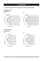
Pressure drops
(see graph for pressure drops at nominal flow rate)
Kv
17


