


Systemair NOVA drive 370
|
11
DIR
0V
Direction
CW/CCW
Motor parameters
Break
Reset / Automatic test
B
A
0V
Pot. meter
C
A
B
D
F
E
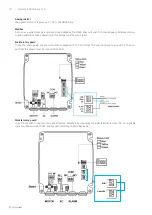
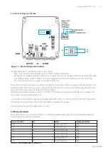
5.2.3 Motor settings and direction
Figure 11 – Motor settings and direction
The dip settings (A) of the motor must be set accordingly:
•
Dips 1-3 are used for motor selection. Refer to Table 5 for more information.
•
Dip 4 is used for break functionality. When set to ON when the motor is stopped it will break by shorting the wind-
ings making it harder to rotate. When set to OFF it is easier to turn the rotor, when the motor is not running.
•
Dip 5 must be set to OFF. The usage is reserved for fault reset.
When DIR in (B) is left unconnected the motor will rotate in one direction. If DIR is connected to 0V it will rotate in the
opposite. Connect DIR to 0V if you wish to change the direction the motor rotates. Note that the direction will change
the next time the motor starts, not when it is already rotating.
Maximum speed can be reduced and set as 50-100% of the maximum speed given by the dip switch settings. This
can be done using the potentiometer in (C).
It is possible to reset faults and warnings by toggling dip switch 5 (off->on->off) in less than 5 seconds. This will also
set the inverter to use analog control unless new Modbus messages are received.
If using the alarm signal in the relay connect it in (E).
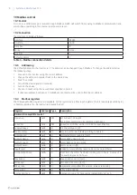
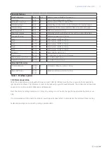
6 Motor parameters
Motor parameters are set using dip switches 1-3. A table is depicted bellow with the correspondence between dip
switches and motor parameters selected.
Dip switch (123)
Id
Motor
MaxSpeed (RPM)
000
0
90TYD-S214-M
200
100
1
90TYD-S214-M
250
010
2
120-TYD-S214-M
250
110
3
120-TYD-S214-M
300
001
4
120-TYD-S214-M
350
101
5
120-TYD-S214-L
300
011
6
120-TYD-S214-L
350
Table 5 – Motor parameters selection


