background image


Operation 

12 

MRH 06.04.2017 


DANGER 

Hazard from crushing/shearing by the hatch cover! 
The hatch cover can be stopped in any position by turning the actuator`s service switch to middle (0) posi-
tion.  


Check the functioning of system – observe instructions of actuator, especially intermittence and time of pres-
ence of control voltage (see also Appendix 4).  


After checking set the actuator`s service switch to position 1 (ready to open) and secure it. 
 

9


Operation 

9.1


Operation/use generally 


Only use the fan in accordance with this operating instruction and the operating instructions of motor. 


Control the fan during operation for correct function. 


Switch the fan off as planned. 


WARNING 

Hazard from electrical voltage and flying parts! 
Errors occurring can lead to personal and/or property damage! 

Switch the fan off as planned: 


In cases of a non-typical noise from bearings, vibrations, pressure pulsation. 


In case of overcurrent, overvoltage or temperature (nameplate). 


NOTE 

At single speed motors with nominal power from incl. 5,5 kW (D400V) we recommend “star – delta” start-
ing or soft start. For this purpose, all 7 wires are led to connection box/service switch. 

 
9.2 

Emergency use (use in case of fire) 

Serially equipped MRH is intended for emergency use only. Access to hazardous zone is allowed and possible with ob-
serving safety measures for maintenance and service only.  


DANGER 

Hazard from touching impeller, if not covered with protective grid! 
The outlet protective grid is serially provided.  


DANGER 

Hazard from crushing/shearing by the hatch cover! 
The hatch cover can be stopped in any position by turning the actuator`s service switch to middle (0) posi-
tion.  

Observing safety measures, it is to assure: 


Safety components must not be bypassed or put out of function. 


Prevent sucking of foreign particles, this can destroy the fan. 


The fan may operate only within the limits declared on the nameplate.  


In case of fire, bridging of motor protective devices is necessary to assure operation. Switch on max. speed even 
after eventual short supply cut off must be assured.  

Summary of Contents for MRH 1000

Page 1: ...MRH Installation and Operating Instructions for English Originalversion ...

Page 2: ...t our products are subject to a natural wear and ageing process All rights are with Systemair also for the event of applications for protective rights Any powers of use such as copying and forwarding rights are with us An exemplary configuration has been shown on the title page The product supplied can therefore deviate from the illustration The original operating instructions have been written in...

Page 3: ...ion 9 7 1 Residual current circuit breaker 10 7 2 Connection of thermal protection 10 8 Commissioning 10 8 1 Preconditions 10 8 2 Commissioning 11 9 Operation 12 9 1 Operation use generally 12 9 2 Emergency use use in case of fire 12 9 3 Dual use of hatch fan daily powered ventilation emergency use 13 9 4 Dual use of hatch fan daily natural ventilation emergency use 13 10 Maintenance troubleshooti...

Page 4: ...not covered with protective grid This warning identifies situations with a danger for life from touching impeller Failure to comply with this warning leads to the risk of death or serious injuries DANGER Hazard from crushing shearing from closing hatch cover This warning identifies situations with a danger for life from closing the hatch cover Failure to comply with this warning leads to the risk ...

Page 5: ...d mechanical protective devices During mounting commissioning maintenance and control secure the place of mounting against unauthorised access Observe rules for safe work Protective working gloves protective working shoes safety goggles safety helmet are part of personal protective equipment Depending on object additional protective equipment may be necessary Safety components must not be by passe...

Page 6: ...wind load WL 1500 EN 12101 2 3 The fans are suitable for extraction of clean air air with a low dust and grease content The maximum permissible operating data on the name plate apply for an air density ρ 1 2 kg m sea level and a maximum air moisture of 80 Temperature of medium 20 up to 55 C respectively according temperature time class of the axial fan In case of fire all motor protective devices ...

Page 7: ...ing missing rivets screws or covering caps WARNING Electrical hazard from damaged connection cable or connections Do not use the connection cable service switch or impeller for transport or hoisting WARNING Hazard of impact if the device falls down Transport the device carefully and with appropriate hoisting device Wear a safety helmet and safety goggles Only put the device at unpacking on its bas...

Page 8: ...tion on the nameplate 6 2 Preconditions for installation MRH must be installed on roofs They can be mounted on a flat or inclined roof on an appropriate roof frame observe load capacity stiffness insu lation The sidebars are adjustable to roof pitch Possibility to adjust depends on the height position of sidebars Installation on flat surface e g concrete or through the roof Extremely wind or turbu...

Page 9: ... of service switch The quality and installation of cables for electrical connection must ensure uninterrupted energy supply even in case of fire Inside fire zone use only certified cable Connecting possibility see Appendix 3 Electrical data on the fan s nameplate must comply with the provided mains connection Voltage tolerance according to IEC 38 6 10 Hatch cover it is opened by one or two 24VDC o...

Page 10: ...ker Use universal RCDs type B or B in case of speed control with frequency converter See also specific fan instruc tions 7 2 Connection of thermal protection CAUTION Property damage as a result of motor overheating The motor can overheat and be destroyed if the PTC not been connected PTC always connect to a motor protective device 8 Commissioning 8 1 Preconditions Mounting and electrical connectio...

Page 11: ...d is serially provided WARNING Hazard from bursting parts When checking the direction of rotation wear safety goggles WARNING Hazard from electrical voltage and flying parts Errors occurring can lead to personal and or property damage Observe 5 safety rules for the electrical expert disconnect from the power supply all pole prevent switching on again test absence of voltage earthing and short circ...

Page 12: ...voltage or temperature nameplate NOTE At single speed motors with nominal power from incl 5 5 kW D400V we recommend star delta start ing or soft start For this purpose all 7 wires are led to connection box service switch 9 2 Emergency use use in case of fire Serially equipped MRH is intended for emergency use only Access to hazardous zone is allowed and possible with ob serving safety measures for...

Page 13: ... for speed control in the instruction of the fan usually it is recommended a combina tion of frequency converter and appropriate all pole sinus filter or minimum dU dt filter At frequency controlled units additional EMC protection of cable and service switch could be needed on request Subsequently fitting of EMC shielded cable from motor to connection box service switch is connected with disassemb...

Page 14: ...y the hatch cover The hatch cover can be stopped in any position by turning the actuator s service switch to middle 0 posi tion WARNING Hazard from electrical voltage Trouble setting and service only by a trained electrician or trained and instructed qualified personnel Observe rules for safe work while troubleshooting Observe 5 safety rules for the electrical expert disconnect from the power supp...

Page 15: ...ble area of the fan curve Check operating point and system design Consult cus tomer service of the manufacturer Damage or dust layer on impeller Clean the impeller if necessary balance it or replace it The hatch cover doesn t fully open 70 ore fully close Obstacle One or both actuators is faulty MRH 1120 Check if the actuator is are powered Limit switch indicates if the end position is reached Rep...

Page 16: ...iggering device Check it for function Test of functions Test all functions of system from control panel as well as signal lights Test of hatch opening closing Check the joints of actuator and hatch cover are properly fastened Check if smoothly opens closes Check the safety measures protective elements signs guards Accessories air ducts air louvers flaps sound at tenuators 5 5 1 Check accessible du...

Page 17: ...UTION Danger from cutting edges and impact Wear protective gloves when dismounting Dismount carefully WARNING Hazard from falling parts When selecting the hoisting device observe the weight weight information on the name plate Carefully disconnect all wires Remove the fan from duct Carefully remove the fastening material Lift the MRH with an appropriate hoisting device on the provided lifting eyes...

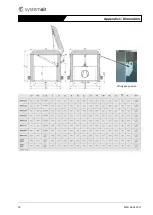
Page 18: ...18 MRH 06 04 2017 Appendix 1 Dimensions Lifting eye position ...

Page 19: ...ight choose considering access snow depo sition wind pitch Roof insulation and flashing is not shown in the installation examples Appendix 2 Installation examples 1 Three height positions of sidebars 0 250 500 mm from the bottom 2 The sidebars adjust to the roof pitch and fasten all bolts 2 or 3 bolts each sidebar depending on the sidebar position 3 Fasten the bars to the roof frame with bolts or ...

Page 20: ...4 5 400 630 0 0 12 250 0 12 500 0 2 min 21 max 33 MRH HG 1 2 3 4 5 710 800 0 0 12 250 0 12 500 0 2 min 20 max 31 MRH HG 1 2 3 4 5 900 1000 0 0 9 250 0 9 500 0 2 min 14 max 21 MRH HG 1 2 3 4 5 1120 0 0 9 250 0 9 500 0 2 min 12 max 19 The sidebars can be upon request ordered to meet specific roof pitch ...

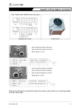
Page 21: ...x1 5 PTC d max 1 5 mmq D max 10 mm 3 M25x1 5 When choosing AES exhaust air and smoke extraction control accessory please observe serial connecting capability of the fan s service switch Appendix 3 Wiring diagram connection 1 2 3 1 2 3 DVAX DVAX BPN DVAX BPF 1000D4 M DVAX DVAX BPN DVAX BPF 1000D4 L DVAX DVAX BPN DVAX BPF 1120D6 L AXC B AXC F 22 kW 930637 MZ0651800777 930638 MZ0751800644 DVAX DVAX B...

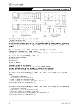
Page 22: ...h Position 0 stop NO opened contact NC closed contact SAFETY POSITION Position 1 open hatch cover NO closed contact NC opened contact WARNING Position 2 close hatch cover NO opened contact NC closed contact DANGER Connection of actuator s internal floating limit switches in the actuator s service switch 1 actuator up to MRH 1000 drawn position closed hatch 1 2 opened 2 3 closed in closed hatch pos...

Page 23: ... protective grid The outlet protective grid is serially provided DANGER Hazard from crushing shearing by the hatch cover The hatch cover can be stopped in any position by turning the actuator s service switch to middle 0 posi tion Appendix 5 Mechanical hazards safety warnings ...

Page 24: ......

Reviews: