SystemAir EVC-RZHC-HUB Installation Manual Download Page 2

EVC-RZHC-HUB_Room-Zone-HUB with cabinet_inst_GB_tbm_27.11.2019


2


09.12.19


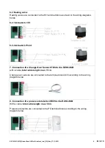
Electrical connection to room controller RC-C3DOC


2x Microfit, DC supply 24V, Modbus RTU and Signal wires, 
cable EVC-RCC-10 Room controller-connection cable 10m 
or EVC-RCCE-10 extension cable 10m for EVC-RCC-10, 
max. 50 m


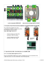
Electrical connection to volume flow controller supply air and extract air 

2x RJ12, DC supply 24V and Modbus RTU,


Cable EVC-DC-10_Damper-connection cable 10 m, max. 30 
m


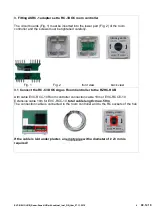
Electrical connection to CO2, VOC, RH- Sensor, heating valve, cooling 
valve, Change-Over Sensor, presence detector, condensation sensor, 
window contact


Screw terminals, 1,5 mm², 3x 4-pole, 1x 3-pole, 2x double-
pole


Before installation and operation, these instructions must be read and all 
instructions given must be observed!


Important information:


- If the device is operated outside the specification range, all warranty claims are void. 
- This device is only to be used for the specified purpose. The corresponding safety regulations of the VDE, 
the federal states, their monitoring bodies, the TÜV and the local power supply companies must be observed. 
- The buyer must ensure compliance with the construction and safety regulations and avoid all types of 
hazards. 
- For defects and damages caused by improper use of this device, no warranties and liability will be 
assumed.  
- Consequential damages caused by faults on this device are excluded from warranty and liability. 
- The devices may only be installed by qualified personnel. 
- Only the technical data and connection conditions of the assembly and operating instructions supplied with 
the device apply. Deviations from the catalogue presentation are not additionally listed and are possible in the 
sense of technical progress and continuous improvement of our products. 
- If the user modifies the devices, all warranty claims are void. 
- The housing and housing accessory dimensions may have small tolerances to the specifications in these 
instructions. 
- Changes to these documents are not permitted. 
- Please, also observe the operating and assembly instructions of all components to be connected. 


Summary of Contents for EVC-RZHC-HUB

Page 1: ...using the base board is also suitable for mounting on DIN rail Dimensions mm Technical data Supply voltage DC 48 V Possible operating range 30 48 V DC Power Consumption 4 W without connected devices Operating temperature range 0 40 C Relative humidity during operation 10 90 r H non condensing Storage conditions 20 40 C non condensing Protection class III safety extra low voltage Enclosure class IP...

Page 2: ...pose The corresponding safety regulations of the VDE the federal states their monitoring bodies the TÜV and the local power supply companies must be observed The buyer must ensure compliance with the construction and safety regulations and avoid all types of hazards For defects and damages caused by improper use of this device no warranties and liability will be assumed Consequential damages cause...

Page 3: ...rd can be removed from the housing The board is then suitable for mounting on a DIN rail 2 Connection of the RZHC HUB to the master cabinet EVC MC A free network port of the main switch cabinet EVC MC is connected to the RZHC HUB at the Controller BACnet Modbus port Connection via RJ45 network cable Total cable length max 150 m AWG 26 7 Alternatively a network installation cable network connector ...

Page 4: ...must be tightened carefully Fig 1 Fig 2 front view back view 3 1 Connect the RC C3 DOC Argus Room Controller to the RZHC HUB with cable EVC RCC 10 Room controller connection cable 10m or EVC RCCE 10 Extension cable 10m for EVC RCC 10 total cable length max 50 m The connection cable is connected to the room controller and to the RC sockets of the hub If the cable is laid under plaster an empty pipe...

Page 5: ...X D3 MOD to RZHC HUB The volume flow controllers are each connected to the RZHC hub with a 10 m EVC DC 10 damper connection cable total cable length max 30 m Connect exhaust air volume flow controller to VAV ETA socket Connect supply air volume flow controller to VAV SUP socket 5 connection CO2 VOC or humidity sensor to the RZHC HUB with a cable total cable length max 50 m Only one CO2 VOC humidit...

Page 6: ... 5 1 1 Connection of the wall mounted CO2 sensor 14904 5 1 2 Connection of the wall mounted CO2 sensor with display 14905 5 1 3 Connection of the CO2 duct sensor 14906 5 2 VOC Sensors VOC sensors are connected to the terminal block CO2 VOC according to the wiring diagrams below 5 2 1 Connection of the wall mounted VOC Room sensor 156812 5 2 2 Connection of the VOC duct sensor 156813 ...

Page 7: ... connected to the terminal block CO2 VOC according to the wiring diagram below 6 Connection of a cooling or heating valve to the RZHC HUB with a cable total cable length max 50 m 6 1 Cooling valve Cooling valves are connected to the CV terminal block as shown in the wiring diagrams below 6 1 1 Actuator 0 10V 6 1 2 Actuator 2 Point ...

Page 8: ...2 Actuator 2 Point 7 Connection of a Change Over Sensor 7284 to the RZHC HUB with a cable total cable length max 15 m Change over sensors are connected to the terminal block COS according to the wiring diagram below 8 Connection of a presence detetector 6995 to the RZHC HUB With a cable total cable length max 50 m Presence detectors are connected to the PD terminal block according to the wiring di...

Page 9: ...RZHC HUB With a cable total cable length max 50 m Condensation sensors are connected to the terminal block CD according to the wiring diagram below 10 EU Declaration of Conformity This product carries the CE Mark For more information please visit www systemair de Contact Systemair GmbH Seehöfer Straße 45 97944 Boxberg Germany ...

Reviews: