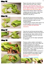
Step 19
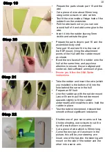
Step 20
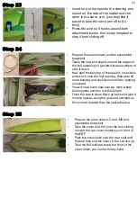
Step 21
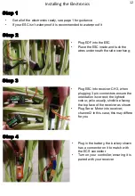
Step 22
•
Prepare the parts shown: part 15 and the
wire
•
Cut a piece of wire about 30mm long
using some scissors or wire cutters
•
Test fit the wire inside of hinge hole of the
rudder from the underside.
•
Pull the wire back out so you can see
around half of it and add some glue to the
wire.
•
Insert it into the rudder leaving 5mm
visible and activate the glue
•
Prepare the parts shown: part 16 and the
assembled body shell
•
Take part 16 and test fit it to the rear of
the EDF mount, lining the attachment
points of the Hull with the rudder mount
as shown.
•
Bond the two faces of the rudder onto the
hull at the same time, and pay close
attantion to ensure they are aligned and
centered. Add sufficient ammount of glue.
•
Ensure you follow the G&A Guide
instructions
•
Take the rudder and insert the wire (which
you installed to the bottom of it) into the
hole behind the servo in the hull
•
Prepare an M1 bolt
•
Line the rudder up with the rudder mount
(you will have to pull the rudder mount
upwards slightly to fit the rudder
underneath) and install the bolt to hold the
rudder in place
•
Test the rudder movement, it should feel
smooth without significant resistance
•
Shorten one of your servo arms so it has
4 holes showing, use scissors to cut the
tip off (result shown in pictures)
•
Cut a piece of wire which is 50mm long
•
Curve the two tips of it as shown in the
picture, this will be your steering arm
•
Insert one of the tips into the steering arm
mount on the side of the rudder and the
other into a servo arm.
10


