Synapse GDR216 Installation And Operation Manual Download Page 21


21 

What information is 

available in an 

event? 

The message consists of the following items; 

1)


A message string to show what has happened in text, for example: 
“INP_LOSS”, “REF_LOSS”, “INP_RETURN”.  

2)


A tag that also shows what happens, but with a predefined number: 
e.g. 1 (= loss of input), 2 (= loss of reference), 129(= 1+128 = 
return of input). For a list of these predefined tags see the table on 
the next page. 

3)


A priority that marks the importance of an event. This value is 
defined by the user and can have any value between 1 and 255, or 
0 when disabled. 

4)


A slot number of the source of this event.


The Message String 

The message string is defined in the card and is therefore fixed. It may 
be used in controlling software like Synapse Set-up to show the event. 


The Tag 

The tag is also defined in the card. The tag has a fixed meaning. When 
controlling or monitoring software should make decisions based on 
events, it is easier to use the tag instead of interpreting a string. The 
first implementation is the tag controlled switch in the GPI16. In cases 
where the event marks a change to fault status (e.g. 1 for Loss of 
Input) the complement is marked by the tag increased by 128 (80

hex

(e.g. 129 (81

hex

) for Return of Input).
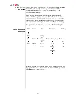


Defining Tags 

The tags defined for the card are: 

Event Menu Item 

Tag 

Tag 

Description 

Announcements 

0 or NA 

0 or NA 

Announcing of report 
and control values 

Input_A 

01

hex

 =INP_LOST 

81

hex

 =INP_RETURN 

SDI input A lost or 
returned 

Lock-status_A 

11

 hex

 =PLL_LOCKED


91

 hex

 =PLL_UNLOCKED 

PLL input A locked 
or unlock


Input_B 

12

 hex

 =INP_LOST 

92

 hex

 =INP_RETURN 

SDI input B lost or 
returned 

Lock-status_B 

51

 hex

 =PLL_LOCKED


d1

 hex

 =PLL_UNLOCKED 

PLL input B locked 
or unlock 

Active_Out_A 

19

 hex

 =IN_B_->_OUT_A


99

 hex

 =IN_A_->_OUT_A 

Active output A is 
In_B or In_A 

Active_Out_B 

1a

 hex

 =IN_A_->_OUT_B


9a

 hex

 =IN_B_->_OUT_B 

Active output B is 
In_A or In_B 


The Priority 

The priority is a user-defined value. The higher the priority of the 
alarm, the higher this value. Setting the priority to Zero disables the 
announcement of this alarm. Alarms with priorities equal or higher 
than the Error Threshold setting of the RRC will cause the error LED 
on the Synapse rack front panel to light. 


The Address 

Together with the message string or the tag, the slot number or address 
of the card is relevant to be able to assign the event to a certain card. 

Summary of Contents for GDR216

Page 1: ...GDR216 3Gb s HD and SD dual input distribution amplifier with 8 reclocked outputs per channel ASI DVB compatible Installation and Operation manual...

Page 2: ...Hercules 28 NL 5126 RK Gilze The Netherlands Phone 31 161 850 450 Fax 31 161 850 499 E mail Info axon tv Web www axon tv TECHNICAL MANUAL GDR216...

Page 3: ...extremely high or low temperatures NEVER operate this product in an explosive atmosphere Warranty Axon warrants their products according to the warranty policy as described in the general terms That m...

Page 4: ...nu 13 Introduction 13 Mode 13 Input_sel 13 PLL_set_A 14 Reclocker_A 14 Mute_A 14 PLL_set_B 14 Reclocker_B 14 Mute_B 14 GPO 0 15 GPO 1 15 GPO 2 15 Switch Back 15 HDMI1 Format 15 HDMI1 DVI Mode 16 HDMI1...

Page 5: ...an event 20 Events 20 Announcements 20 Input_A 20 Lock Status_A 20 Input_B 20 Lock Status_B 20 Active_Out_A 20 Active_Out_B 20 What information is available in an event 21 The Message String 21 The Ta...

Page 6: ...control panel is also used to back up and restore card settings Please refer to the RRC18 RRC10 RRC04 RRS18 and RRS04 manuals for a detailed description of the local control panel the way to set up re...

Page 7: ...mature failure from components mounted on the board Placing the card The Synapse card can be placed vertically in an SFR18 frame or horizontally in an SFR04 and SFR08 frame Locate the two guide slots...

Page 8: ...used to change settings An overview of the settings can be found in chapter 5 6 and 7 of this manual Front Panel Control Front Panel Display and Cursor Settings are displayed and changed as follows U...

Page 9: ...ate that the SFS10 Settings menu item SDI Format has been selected and shows that it current setting is Auto Pressing the selects the settings item shown in this example SDI Format Pressing or will ch...

Page 10: ...xon Cortex has access to data contained within the Synapse module and displays it on a GUI The software has an intuitive structure following that of the module that it is controlling For operation of...

Page 11: ...t 1 GPI 2 select input 2 GPO 0 Crossed mode or straight mode status GPO 1 input 1 status GPO 2 input 2 status 2x2 or 2x1 function 2x1 8 or 1x1 16 function Compatible with SD SDI 270 Mbit s SMPTE 259M...

Page 12: ...NPUT GPI OUT INTERNAL SYNAPSE BUS 3Gb s HD SD OUT 2 3Gb s HD SD OUT 4 3Gb s HD SD OUT 5 3Gb s HD SD OUT 7 3Gb s HD SD OUT 6 3Gb s HD SD OUT 8 3Gb s HD SD OUT 9 3Gb s HD SD OUT 11 3Gb s HD SD OUT 10 3G...

Page 13: ...e card works in default in 1 channel mode input A is set to all outputs In 2 channel mode input A is set to outputs A1 till 3 and input B is set to outputs B1 till B3 In Crossed the card works inverte...

Page 14: ...unlock will mute input A in case the PLL rate of input A is not available The Default setting is Off PLL_set_B The GDR216 is capable of re clocking a range of 3Gbit s HD and SD SDI transport stream b...

Page 15: ...lue 0 indicates that the card is in crossed mode Value 1 indicates that the card is operating in normal mode GPI 1 Lets the GPO indicate the Value of GPI 1 GPI 1 inv Lets the GPO indicate the inverted...

Page 16: ...s for HDMI1 Format HDMI2 DVI Mode With these settings you set SFP HDMI output B to either DVI Mode or HDMI Mode Default is DVI Mode HDMI2_Mute_All Here you can mute all audio on SFP HDMI output B Off...

Page 17: ...of locking rates is as follows 270 Mb s 1485 Mb s and 2970 Mb s SDI Input_B This status item indicates the presence of a valid SDI signal on input B SDI_Input_B indicates if an input signal is Present...

Page 18: ...ecified port on SFP output module A is Too_High High OK Low or Too_Low Can also be NA in case of an input module or no module is inserted Port1 2 Bias These status items indicate the current laser bia...

Page 19: ...Port3 4 Power Stat These indicate whether the output power of the specified port on SFP output module B is Too_High High OK Low or Too_Low Can also be NA in case of an input module or no module is in...

Page 20: ...R216 are as follows Announcements Announcements is not an event This item is only used for switching the announcement of status changes on off 0 off other on Input_A Input A status can be selected bet...

Page 21: ...nge to fault status e g 1 for Loss of Input the complement is marked by the tag increased by 128 80hex e g 129 81hex for Return of Input Defining Tags The tags defined for the card are Event Menu Item...

Page 22: ...tly or has a hardware failure Input A LED This LED indicated the presence of a valid video signal on input A Input B LED This LED indicated the presence of a valid video signal on input B Connected LE...

Page 23: ...INPUT GPI OUT INTERNAL SYNAPSE BUS 3Gb s HD SD OUT 2 3Gb s HD SD OUT 4 3Gb s HD SD OUT 5 3Gb s HD SD OUT 7 3Gb s HD SD OUT 6 3Gb s HD SD OUT 8 3Gb s HD SD OUT 9 3Gb s HD SD OUT 11 3Gb s HD SD OUT 10 3...

Page 24: ...displays the pinout of these backpanels BPH37 BHX37 relay bypass relay bypass SDI OUTPUT 1A SDI OUTPUT 2A SDI OUTPUT 3A SDI OUTPUT 4A SDI OUTPUT 5A SDI OUTPUT 6A SDI OUTPUT 7A SDI OUTPUT 8A SDI INPUT...

Page 25: ...DI OUTPUT 1B SDI OUTPUT 2B SDI OUTPUT 2B SDI OUTPUT 3B SDI OUTPUT 3B SDI OUTPUT 4B SDI OUTPUT 4B SDI OUTPUT 5B SDI OUTPUT 5B SDI OUTPUT 6B SDI OUTPUT 6B SDI OUTPUT 7B BPH42 BHX42 relay bypass relay by...

Page 26: ...26 GPI I O RJ45 connector with the following pinning...

Reviews: