


SG
-
S200, SG
-
S400, SG
-
S500
2
ProxySG
Quick Start Guide
1 — Unpack the Appliance
Unpack the shipping package for the appliance and verify it
includes the following:
2 — Connect Cables
It is recommended that you plug in cables, verify LEDs, and
configure and license the appliance before mounting it in an
equipment rack. Make sure the appliance is on a flat, level
surface when performing the initial configuration. If you would
rather mount the appliance before performing configuration
tasks, skip to
The following procedure describes a typical in-line deploy
-
ment for SG
-
S200, SG
-
S400, and SG
-
S500 appliances (as
). For information on other deployments,
see the ProxySG software documentation, available at:
NOTE:
Network cables are not included with the appliance.
Make sure to use only straight-through Ethernet cables.
Category 5E cables or better are recommended for
1000Base-T operation. Category 6A cables are
recommended for 10GBase-T operation.
To deploy the appliance and connect cables:
1. Disconnect the Ethernet cable (if there is one) between
the LAN switch and WAN router.
2. Connect the appliance to the LAN switch:
For
SG
-
S200
and
SG
-
S400
appliances, connect an
Ethernet cable to the appliance’s
LAN 2:0
port and con
-
nect the other end of the cable to the LAN switch.
For
SG
-
S500
appliances, connect an Ethernet cable to
the appliance’s
LAN 1:0
port and connect the other end
of the cable to the LAN switch.
The appliance auto-negotiates 10/100/1000 Base-T
speed and duplex settings.
3. Connect the appliance to the WAN router:
For
SG
-
S200
and
SG
-
S400
appliances, connect an
Ethernet cable to the appliance’s
LAN 2:1
port and con
-
nect the other end of the cable to the WAN router.
For
SG
-
S500
appliances, connect an Ethernet cable to
the appliance’s
LAN 1:1
port and connect the other end
of the cable to the WAN router.
4. Connect an Ethernet cable to the appliance’s
MGMT 0:0
port and connect the other end of the cable to the man
-
agement network switch.
5. Connect the included null-modem cable to the appli
-
ance’s
DB9 Serial
port and connect the other end of the
cable to a serial terminal or workstation with terminal
emulation software. The serial connection is used to per
-
form the appliance’s initial configuration.
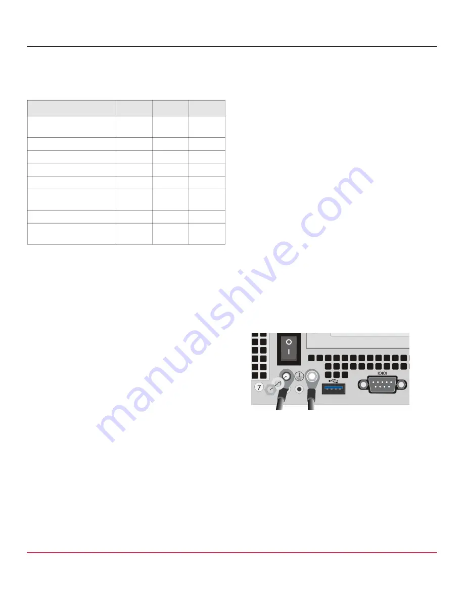
6. For
SG
-
S500 appliances
, attach the lug-equipped end of
the included grounding wire (10 AWG) to both grounding
studs on the appliance, securing it with the star washers
and M5 nuts. Attach the other end of the grounding wire
to a proper earth-ground.
7. Connect the appliance to a power source:
For
SG
-
S200
appliances, connect the included power
cord to the appliance’s power inlet and connect the
other end of the power cord to a power source.
For
SG
-
S400
and
SG
-
S500
appliances, connect the
included power cords to the appliance’s power inlets
and connect the other ends of the power cords to a
power source.
Appliance
SG
-
S200 SG
-
S400 SG
-
S500
AC power cords
(number included)
1
2
2
Null-modem serial cable
√
√
Grounding hardware
√
2- and 4-post slide-rail kit
optional
√
√
2-post fixed rail
√
Accessing Appliance
Documentation
√
√
√
Software License Agreement
√
√
√
Hardware Warranty
Information
√
√
√


