


1-7-5
T5307EA
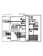
Notes: Screen Control FBT --- MAIN CBA
F.B.T= Fly Back Transformer
Use the Remote Control Unit
1. Degauss the CRT and allow CRT to operate for 20
minutes before starting the alignment.
2. Set the screen control to minimum position. Input
the Black raster signal from RF input.
3. Enter the Service Mode. (See page 1-4-1.)
Dimmed horizontal line appears on the CRT.
4. Press the "VOL
p
" button.
(Press "VOL
p
" then display will change CUT OFF/
DRIVE, VCO adjustment, Analog OSD adjust-
ment).
5. Choose CUT OFF/DRIVE Mode then press "1" but-
ton. This adjustment mode is CUT OFF (R).
6. Press the "CH
o
/
p
" button until the horizontal line
becomes white.
7. Choose CUT OFF/DRIVE mode then press "2" but-
ton. This adjustment mode is CUT OFF (G). Press
"CH
o
/
p
" until the horizontal line becomes white.
8. Choose CUT OFF/DRIVE Mode then press "3" but-
ton. This adjustment mode is CUT OFF (B). Press
"CH
o
/
p
" until the horizontal line becomes white.
9. Input the White Raster Signal from Video In.
10.Choose CUT OFF/DRIVE mode then press "4."
Adjust the RED DRIVE as needed with the CH
o
/
p
buttons to get the following value, X= 286, Y=
294.
11.Choose CUT OFF/DRIVE mode then press "5."
Adjust the BLUE DRIVE as needed with the CH
o
/
p
buttons to get the following value, X= 286.
12.Turn the power off and on again.
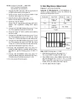
9. Sub-Brightness Adjustment
Purpose: To get proper brightness.
Symptom of Misadjustment: If Sub-Brightness is
incorrect, proper brightness cannot be obtained by
adjusting the Brightness Control.
Note: SYMPTE Setup level --- 7 IRE
1. Enter the Service Mode. (See page 1-4-1.)
Then input SYMPTE signal from RF input.
2. Press MENU button. (Press MENU button then dis-
play will change B R T, C N T, T N T, V-T and
SHP). Select BRT and press CH
o
/
p
buttons so
that the bar is just visible (See above figure).
3. Turn the power off and on again.
Test point
Adj. Point
Mode
Input
---
CH
o
/
p
buttons
---
SYMPTE
7.5IRE
Tape
M. EQ.
Spec.
---
Pattern
Generator
See below
Figure
Black
White
This bar
just
visible
Fig. 4
Summary of Contents for SRC2213
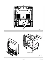
Page 20: ...1 6 2 T5307DC Fig 1 S 1 S 1 1 REAR CABINET S 1 S 1 S 1 S 1 Fig 2 ...
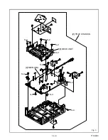
Page 22: ...1 6 4 T5307DC Fig 4 CRT CBA S 5 S 5 S 5 S 5 ANODE CAP 5 CRT ...
Page 25: ...1 6 7 T7308DC Fig 1 ANT S 1 S 1 1 REAR CABINET S 1 S 1 S 1 S 1 Fig 2 ...
Page 27: ...1 6 9 T7308DC Fig 4 S 5 S 5 S 5 S 5 5 CRT CRT CBA ANODE CAP ...
Page 89: ...Packing SRC22194 X 1 S 1 S 4 S 3 S 3 S 2 TAPE TAPE X 4 X 3 X 2 S 6 S 14 FRONT 3 1 6 T7308PEX ...
Page 108: ...Printed in Japan 2002 02 20 HO SRC2213 SRC22134 SRC22194 T5307UH 8UJ 7308UJ ...


