


1-7-2
T5307EA
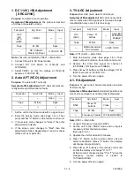
1. DC 114V (+B) Adjustment
[ SRC22194 ]
Purpose: To obtain correct operation.
Symptom of Misadjustment: The picture is dark and
unit does not operate correctly.
Note: J192(+B), J213(GND), VR601 --- Main CBA
1. Connect the unit to AC Power Outlet.
2. Connect DC Volt Meter to J192(+B) and
J213(GND).
3. Adjust VR601 so that the voltage of J192(+B)
b114
±
0.5V DC.
2. Auto AFT (VCO) Adjustment
Purpose: To operate AFT correctly.
Symptom of Misadjustment: AFT does not work cor-
rectly and/or synchronization is faulty.
1. Set the unit to the Video mode with no signal input.
2. Enter the Service mode. (See page 1-4-1.) Then
press number "3" button on the remote control unit.
3. If the screen color changes to "Green" then this
adjustment is finished.
4. If the screen color changes to "Red" then this
adjustment is failed. Repeat steps 1 and 2 or check
relative circuit or parts (IC).
3. TV AGC Adjustment
Purpose: Set AGC (Auto Gain Control) Level.
Symptom of Misadjustment: AGC does not synchro-
nize correctly when RF input level is too weak and pic-
ture distortion may occur if it is too strong.
Note: J191 (AGC) --- Main CBA
1. Enter the Service mode. (See page 1-4-1.) Then
press number 2 button on the remote control unit.
2. Receive the Color Bar signal for channel 4
(67.25MHz). (RF Input Level: 60dB
µ
V)
3. Press CH
o
/
p
buttons so that the voltage of J191
(AGC) b2.8V
±
0.3V DC.
4. Turn the power off and on again.
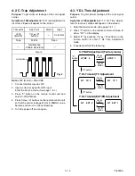
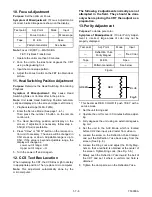
4-1. H Adjustment
Purpose: To get correct horizontal position and size
of screen image.
Symptom of Misadjustment: Horizontal position and
size of screen image may not be properly displayed.
Note: R583 --- Main CBA
1. Connect Frequency Counter to R583.
2. Set the unit to the VIDEO mode and no input is
necessary. Enter the Service mode.
(See page 1-4-1.)
3. Operate the unit for at least 20 minutes.
4. Press "2" button on the remote control unit and
select H-Adj Mode. (Press "2" button, then display
will change H-Adj and AGC.)
5. Press CH
o
/
p
buttons on the remote control unit
so that the display will change "0" to "7."
At this moment, choose display "0" to "7" when the
Frequency counter display is closest to
15.734kHz
±
300Hz.
6. Turn the power off and on again.
Test point
Adj. Point
Mode
Input
J192
(+B)
J213
(GND)
VR601
---
-----
Tape
M. EQ.
Spec.
---
DC Voltmeter
Plastic Tip Driver
+114
±
0.5V DC
Test point
Adj. Point
Mode
Input
---
---
Video
-----
Tape
M. EQ.
Spec.
---
---
---
Test point
Adj. Point
Mode
Input
J191
(AGC)
CH
o
/
p
buttons
---
Color Bar
67.25MHz
60dB
µ
V
Tape
M. EQ.
Spec.
---
Pattern Generator
DC Voltmeter
+2.8
±
0.3V DC
Test point
Adj. Point
Mode
Input
R583
CH
o
/
p
buttons
Video
---
Tape
M. EQ.
Spec.
---
Frequency Counter
15.734kHz
±
300Hz
Summary of Contents for SRC2213
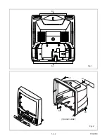
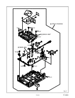
Page 20: ...1 6 2 T5307DC Fig 1 S 1 S 1 1 REAR CABINET S 1 S 1 S 1 S 1 Fig 2 ...
Page 22: ...1 6 4 T5307DC Fig 4 CRT CBA S 5 S 5 S 5 S 5 ANODE CAP 5 CRT ...
Page 25: ...1 6 7 T7308DC Fig 1 ANT S 1 S 1 1 REAR CABINET S 1 S 1 S 1 S 1 Fig 2 ...
Page 27: ...1 6 9 T7308DC Fig 4 S 5 S 5 S 5 S 5 5 CRT CRT CBA ANODE CAP ...
Page 89: ...Packing SRC22194 X 1 S 1 S 4 S 3 S 3 S 2 TAPE TAPE X 4 X 3 X 2 S 6 S 14 FRONT 3 1 6 T7308PEX ...
Page 108: ...Printed in Japan 2002 02 20 HO SRC2213 SRC22134 SRC22194 T5307UH 8UJ 7308UJ ...


