background image

6

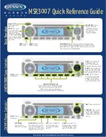
Chart 1: DIP SWITCHES

DIP 1

Alarm timing

DIP 2

Polarity of alarm input

DIP 3

Polarity of flash input

DIP 4

Control panel ON/OFF indication

DIP 5

Sounder and Flash activation mode

DIP 6

Sounder and Flash activation mode

DIP 7

Max number of alarms per day

DIP 8

Tone selection

Chart 2: ALARM DURATION 

DIP 1

ALARM TIMING

ON

(default sitting)

3 minutes

OFF

8 minutes

Chart 3: WIRING

TERMINALS

CONNECTION

1

Negative power supply 0V GND

2

Positive power 13.8V

3

Sounder control (Chart 4)

4

Flash control (Chart 5)

5

ON/OFF indication

6

Anomaly output. Open collector, 0V = anomaly

7

Output for connection of the flash memory 
input with a dry contact (volt-free)

8

N.C. self-protection

9

N.C. self-protection

Chart 4: SOUNDER INPUT POLARITY

DIP 2

TERMINAL 3

SOUNDER STATE

ON 

(default setting)

+12V

Silence

Not connected or 0V (Positive-missing)

Alarm

OFF

+0V

Silence

Not connected or +12V (Negative-missing)

Alarm

SITTING

Chart 5: FLASH INPUT POLARITY

DIP 3

TERMINAL 4

FLASH 

BEHAVIOUR

ON 

(default 

setting)

Not connected or 0V

Flashing

12V

Blocked

OFF

Not connected or 12V

Flashing

0V

Blocked

Chart 6: CONTROL PANEL ON/OFF INDICATION

DIP 4

TERMINAL 5

FLASH BEHAVIOUR (ON/OFF)

ON 

(default 

setting)

+12V

All LEDs flash 3 times

Not connected or 0V

All LEDs stay on for 4 seconds, then 

switch off

OFF

+12V

All LEDs flash 3 times and 1 LED 

keeps on flashing

Not connected or oV

All LEDs stay on for 4 seconds and 

then switch off

Chart 7: SOUNDER AND FLASH ACTIVATION

DIP 5

DIP 6

SOUNDER CONDITION

FLASH CONDITION

ON 

(default setting)

ON 

(default setting)

Controlled by Terminal 3

T. 4 arms – T. 3 starts – T.4 disarms and stops

OFF

ON

Controlled by Terminal 3 Starts with T. 3 and stops with 1 pulse to T. 4 flash reset

ON

OFF

Controlled by Terminal 3

Controlled by T. 3

OFF

OFF

Controlled by Terminal 3

Starts with T. 4 and stops with T. 4 (indipendent)

DIP SWITCHES SETTING

DIP switches can be moved only within the first 12 hours after the board is powered. After this period, 
DIP switches settings will be stored and any further switching will be useless.
  
By disconnecting battery and power supply, DIP switches will return to active for another 12 hours.

Summary of Contents for ECO 800

Page 1: ...the sound of security ECO 800 EXTERNAL SOUNDER ...

Page 2: ...ock tamper devices are series connected and in case of tampering attempt they provide the corresponding notice by opening the contact between the two TAMPER terminals ECO 800 LS ECO 800 LSX description technical features as per ECO 800 ECO 800 X models with double micro anti foam anti stock device against hard hits TECHNICAL FEATURES Voltage Nominal voltage of battery recharge 13 0 13 8 V Minimum ...

Page 3: ...ture From 25 C to 70 C Environmental class Class IV IP degree IP 34 Relative working humidity 20 at 100 of relative humidity Size mm 245x250x80 HxLxD Weight ECO 800 3 066 gr ECO 800 X 3 013 gr ECO 800 LS 3 048 gr ECO 800 LSX 2 995 gr Standards compliance INCERT T031 2014 EN50131 4 2009 DIAGRAM 1 MAXIMUM ACOUSTIC PRESSURE AT 1 M ECO 800 LSX DIP8 IN ON POSITION Angle dB A 1 m 15 102 6 45 103 2 75 10...

Page 4: ...ng the screws provided 7 Battery must have UL94 HB flammability rate 8 Power supply must be of SELV type Attention not to have condensation in the sounder it is important to avoid any air flow inside the duct To such purpose once the sounder is connected seal the hole using some silicon or any other plaster This operation prevents condensation from forming inside the sounder condensation mostly ap...

Page 5: ...the sound of security 5 PICT 3 PICT 4 CONNECTION WITH 2 CONTACTS IN TENSION PICT 5 PICT 6 CONNECTION WITH 1 CONTACT IN TENSION ...

Page 6: ...SH BEHAVIOUR ON default setting Not connected or 0V Flashing 12V Blocked OFF Not connected or 12V Flashing 0V Blocked Chart 6 CONTROL PANEL ON OFF INDICATION DIP 4 TERMINAL 5 FLASH BEHAVIOUR ON OFF ON default setting 12V All LEDs flash 3 times Not connected or 0V All LEDs stay on for 4 seconds then switch off OFF 12V All LEDs flash 3 times and 1 LED keeps on flashing Not connected or oV All LEDs s...

Page 7: ... ned out and turned on again This prevents the sounder from sounding during installation Attention if battery is out of charge voltage is lower than 10 5V in case of alarm the sounder operates for 3 seconds only in order to avoid a deeper discharge Usual sounder working the microprocessor continuously tests the battery voltage If the battery is out of charge voltage is lower than 10 5V the sounder...

Page 8: ...1 04 MANUAL ECO800 ENG REV 04 1472638042 WARRANTY All Sylco products are granted against factory or material defects In order to improve design and quality of the products Sylco reserves the right to modify the products without prior notice All faulty or defective products must be returned to the supplier Certified for Belgium Compliant to T031 standards MADE IN ITALY ...

Reviews: