9
COMMISSIONING AND MAINTENANCE
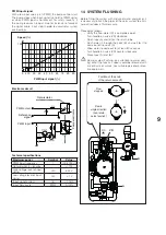
PWM input signal
With a low input value (<5 % PWM), the pump cannot start.
The pump stops when input signal is 5 to 8% of PWM signal
or when PWM signal is not present, for safety reasons. If
the pump receives no input, due for instance to failure of
the signal cable, it will stop in order to avoid solar system
overheating.
Speed (%)
0 5 10
100
20 30 40 50 60 70 80 90 100
PWM input signal (%)
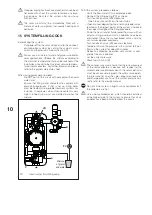
Electronic circuit
PWM output
PWM input
Reference
signal
Opto-isolator
Pump electronics
Technical specifications
Maximum power
Symbol
Value
PWM input frequency
f
100-4000 Hz
Consumption in stand-by
< 1 W
High voltage level of input
signal
UiH
4-24 V
Low voltage level of input
signal
UiL
< 1 V
Input signal current
IiH
< 10 mA
Input Duty cycle
PWM
0-100%
14 SYSTEM FLUSHING
Before filling the system with mixture of water and glycol, it
is necessary to flush the pipes of the solar system to elimi-
nate all residues of fluid or scale.
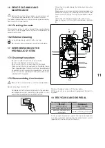
Proceed as follows.
- Verify the flow-meter (C) is completely open
- Turn handle on valve (VR) clockwise
- Open taps (A) and (B) on the return tube
- Flush water in through the cock (B) and wait for it to
come out of the cock (A)
- Allow water to come out for at least 30 seconds
- Turn handle on valve (VR) counter clockwise
- Close taps (A) and (B).
b
During system flushing, pay attention to water com-
ing out of the taps as vapour could be released with
risk of burns or scalds. Use suitable personal protec-
tive equipment.
A
VR
B
RC
90°
0°
R
Position of the knob
of the return valve VR
Flow in
single direction
(non-return
valve function)
Flow
stopped
Commissioning and maintenance


