SWR SolidFlow 2.0 Operating Instructions Manual Download Page 10

Operating Instructions

10

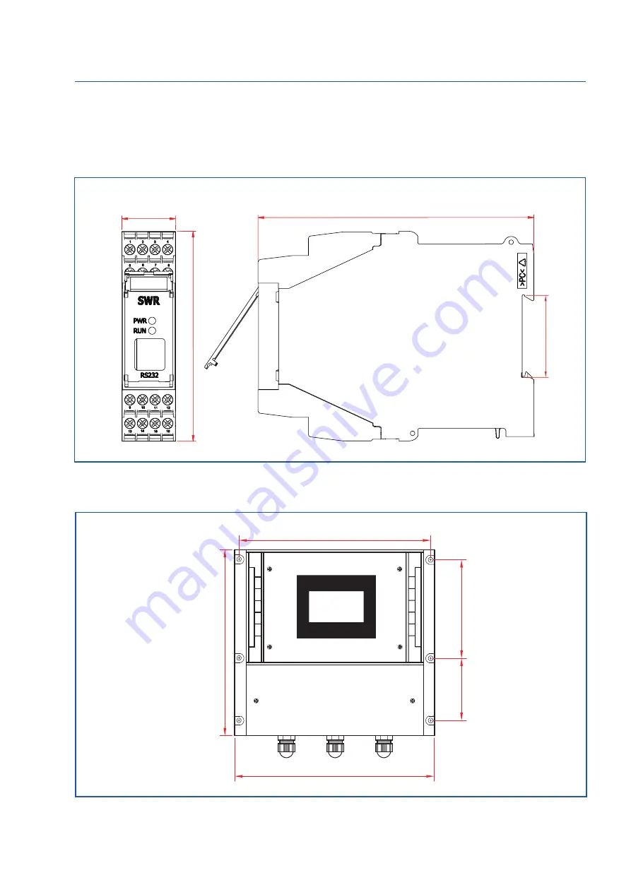
Fig. 9: DIN rail housing for the transmitter

Fig. 10: Field housing for the transmitter

4.4  Mounting the transmitter


The entire transmitter can be installed at a maximum distance of 300 m from the sensor.  
The housing is prepared for installation on a DIN rail according to DIN EN 60715 TH35.

23

90

118

35

90

120

244

254

237

Summary of Contents for SolidFlow 2.0

Page 1: ...EN Operating Instructions SolidFlow 2 0 Solid volume measurement ...

Page 2: ...ransmitter 10 4 5 Use in hazardous areas 12 5 Electrical connection 13 5 1 DIN rail terminal layout 13 5 2 Field housing terminal layout 14 5 3 C1 box terminal layout 15 5 4 C3 box terminal layout 15 6 Operator interface 16 6 1 Differences between the DIN rail and field housing transmitter 16 6 2 Display 17 6 3 PC interface 18 6 4 One or more sensor system 20 6 5 Menu structure 21 7 Start up proce...

Page 3: ...ne Sensor union nut spacer rings sealing ring for adjusting to the wall thickness Installation instructions C1 or C3 box Sensor C1 Box Transmitter max 300 m 2 m 1 24 V 2 GND 3 A 4 B S Earth C1 Box Sensor C1 Box Sensor 16 24 V 15 GND 14 A 13 B Sensor C1 Box Transmitter max 300 m 2 m Fig 1 Overview with C1 box and field housing transmitter Fig 2 Overview with C1 box and DIN rail transmitter ...

Page 4: ...V 2 GND 3 A 4 B Shield The system can be equipped with up to three sensors Different C boxes C1 C3 are used accordingly Fig 3 Overview with C3 box and field housing transmitter Fig 4 Overview with C3 box and DIN rail transmitter Transmitter C3 Box 2 m max 300 m 16 24 V 15 GND 14 A 13 B ...

Page 5: ...nes The special integration of microwave technology together with the metallic pipeline creates a homogeneous measurement field The microwave radiation in the pipeline is reflected by the solid particles and received by the sensor The frequency and amplitude of the received signals are analysed The frequency selected evaluation system ensures that only moving particles are measured and deposits ar...

Page 6: ...manual to denote actions which if not performed correctly may result in death or injury Attention This symbol is used in the operating manual to denote actions which may result in danger to property 3 3 Operational safety The measuring system may only be installed by trained authorised personnel During all maintenance cleaning and inspection work on the pipelines or SolidFlow 2 0 components make s...

Page 7: ...on the pipe It should be installed from the top on horizontal or angled pipelines Note Depending on the application up to 3 sensors can be used on pipeline diameters larger than 200 mm whereby the sensors must be mounted 120 mm apart and offset in relation to each other at an angle of 120 The distances apply to vertical and horizontal installations Ensure that the measurement point is at an adequa...

Page 8: ...e union nut Use a 32 mm open ended spanner to tighten the union nut Fig 7 Install the sensor mount and the plug Spacer ring 1 mm Round seal 19 x 2 Sensor mount Union nut Locking ring Plug q q q q q q q Remove the sealing plug to insert the sensor The sensor is supplied pre assembled for the specified wall thickness or if no wall thickness was specified to a wall thickness of 4 mm Check again that ...

Page 9: ... each Locking ring 20 x 1 2 Padding ring 1 mm Union nut Sensor q q q qq q q 1 2 and align it longitudinally to the pipe axis as shown on the polarisation sticker Fig 8b Then seal the measurement point with the union nut Fig 8b Sensor alignment Flow direction Make sure you install a drip loop with the cable anywhere it may get wet to prevent water flow from reaching the sensor Drip Loops ...

Page 10: ...g 10 Field housing for the transmitter 4 4 Mounting the transmitter The entire transmitter can be installed at a maximum distance of 300 m from the sensor The housing is prepared for installation on a DIN rail according to DIN EN 60715 TH35 23 90 118 35 90 120 244 254 237 ...

Page 11: ...Operating Instructions 11 Fig 11 C1 box dimensions Fig 12 C3 box dimensions Cable gland M 16 x 1 5 ...

Page 12: ...uipment group 2 Equipment category 1 2 Waveguide window zone 20 housing zone 21 For explosive mixtures of air and combustible dust IP code 65 Maximum surface temperature 84 C at Ta 60 C Gas explosion zone identification II 1 2D Ex tD A20 21 IP 65 T84 C II 2G Ex d IIC T5 T3 Equipment group 2 Equipment category 2 Zone 1 For explosive mixtures of air and combustible gases IP code 65 Permitted process...

Page 13: ... contact Alarm relay C Alarm relay NO make contact 1 2 3 4 5 6 7 8 Not used Not used RS 485 Interface Data B RS 485 Interface Data A Sensor connection Cable 4 RS 485 Data B Sensor connection Cable 3 RS 485 Data A Sensor connection Cable 2 Power supply 0 V Sensor connection Cable 1 Power supply 24 V Fig 14 Electrical connection of the transmitter 9 10 11 12 13 14 15 16 1 2 3 4 5 6 7 8 9 10 11 12 13...

Page 14: ... over contact NO make contact C Floating change over contact C common conductor NC Floating change over contact NC break contact D out Digital pulse output Digital pulse output RS 485 A RS 485 interface data A B RS 485 interface data B GND RS 485 interface ground D in1 Digital interface 1 Digital interface 1 D in2 Digital interface 2 Digital interface 2 Sensor Power supply 24 V Cable no 1 GND Powe...

Page 15: ... Instructions 15 5 3 C1 box terminal layout Fig 16 Electrical connection Cable gland M 16 x 1 5 Sensor 1 Transmitter Transmitter Sensor 1 Sensor 2 Sensor 3 Fig 17 Electrical connection 5 4 C3 box terminal layout ...

Page 16: ... between the two versions Function Field housing DIN rail Menu system via PC software yes yes via display yes no Measurement value display current output yes yes Measurement value display pulse output yes no Alarm system relay output yes yes Remote control digital input yes no Autocorrect analogue input yes no Totaliser display yes no via PC software yes yes via display yes no Error output on curr...

Page 17: ...text E for ESC Interrupt the function without making any changes Return Select the function or confirm the input C for Clear Delete a symbol or number If any data has been changed the change will only be taken into account when you exit the complete menu structure and answer Yes when asked if you wish to save the changes For reasons of simplicity a further display menu screen has been dispensed wi...

Page 18: ...chased from SWR For the RS 232 connection to the DIN rail version a special cable and USB converter are supplied USB uses a standard USB A B cable RS 232 and USB are point to point connections which are not bus compatible The ModBus address and baud rate for the front connections cannot be changed and are always ModBus address 1 or the device answers to all addresses Baud rate 9600 8 E 1 When conn...

Page 19: ...h the PC software the transmitter parameters can be saved in a file Save configuration the transmitter parameters can be loaded from a file Load configuration the transmitter parameters can be printed Print configuration the measured values can be logged in a data logger file enter the file name and storage rate and activate the data logger on the online display The software language can be set by...

Page 20: ...will then be registered and a joint average value will be calculated from their measurements The sensors are registered in menu 7 System The existence of several sensors is shown on the online display and in the info area on the display Apart from registering the sensors and the resulting monitoring of several sensors by the transmitter this function has no effect on the operation and will not be ...

Page 21: ...tion 0000 0 000 00 00 000 0 Number representation and decimal point accuracy in the measurement menu 1 5 Set point low Input 0 9999 Throughput rates under this value will not be displayed at the current output This does not concern the display indicator totaliser or pulse output 1 6 Set point hight Input 0 9999 Throughput rates above this value will not be displayed at the current output This does...

Page 22: ...he representation of the calculated raw value in the online window 2 3 Calibration points support points Input 2 5 Number of support points for a linearisation above the operating range 2 4 Calibration Calibration sub menu 2 4 1 P1 value Input Measurement Output measurement in the selected mass time unit 2 4 2 P1 calibration Transfer Raw value Transfer of the current raw value filtered from the ma...

Page 23: ...rement to the uncompensated measurement Both parts are weighted and calculated according to the selected intensity When using this function we recommend only increasing the intensity in 10 steps and to assess the quality of the measurement results in each case A manual parameter set can be set and permanently stored by trained SWR personnel 2 5 1 Conveyor Selection AUS OFF GRV PNE MAN AUS OFF no c...

Page 24: ...t 0 1 99 9 s The value must permanently exceed or fall below the set limit during this time 3 4 Hysteresis Input 0 1 99 9 The alarm continues for as long as the measurement is not smaller or larger than the limit value plus or minus hysteresis 3 5 Operation mode Selection NC NO NC the relay is closed while there is no alarm NO the relay is closed if there is an alarm 3 6 Sensor alarm Selection On ...

Page 25: ...0 22 mA Standard 3 mA 4 4 Upper limit Input 0 22 mA Standard 20 mA 4 5 Alarm value Input 0 22 mA Standard 3 mA 4 6 Calibration 4 mA Selection Set output current The current can be set via key functions and adjusted at the receiving end 4 7 Calibration 20 mA Selection Set output current The current can be set via key functions and adjusted at the receiving end ...

Page 26: ...re selected as the mass unit 10 is selected as the number of pulses per mass unit 1000 kg 10 100 kg A pulse will be emitted every 100 kg To improve readability for connected systems SPC PLC counters etc the maximum pulse frequency is 50 Hz If the number of pulses to be emitted per second exceeds this frequency they will be emitted with a delay ...

Page 27: ...utoCal One of the functions can be executed remotely via the digital input 6 1 2 Normally open close working direction Selection NO NC If necessary invert the value of the input level 6 1 3 Filter Input 0 1 99 9 s Time during which the requested signal must remain pending 6 2 Digital input 2 As digital input 1 ...

Page 28: ...te Seperate Calibration of single sensors Average Average Calibration via the raw value s average value 7 3 Display 7 3 1 Sensor info Selection On Off Show hide Info key 7 3 2 Total Counter Selection On Off Display do not display totaliser value 7 3 3 Backlight Input 0 99 Display lighting in minutes 0 continuously 1 99 min 7 3 4 Contrast 7 4 Baud rate selection 4800 9600 19200 38400 baud Communica...

Page 29: ...ies occur when measuring with different flow rates up to 5 support points can be selected in menu 2 Calibration These support points can then be calibrated with different flow rates 7 2 Adjusting the measurement values The system s additional functions can be set in the following menus Alarms Values for flow rate lower or upper limits can be set in menu 3 Alarm A sensor monitoring alarm can also b...

Page 30: ...eshooting Warning The electrical installation may only be inspected by trained personnel Error Cause Action Measuring system does not work POW LED does not light up RUN LED does not light up Power supply interrupted Check the power supply Cable break Check the connection cables for a possible cable break Defective fuse Replace fuse Defective device Notify SWR and rectify the error as instructed on...

Page 31: ... 237 x 174 W x H x D Weight Approx 2 5 kg Interface RS 485 ModBus RTU USB Cable screw connectors 3 x M16 4 5 10 mm Ø Connection terminals cable cross section 0 2 2 5 mm AWG 24 14 Current output 4 20 mA 0 20 mA load 500 W Switch output measurement alarm Relay with switchover contact Max 250 VAC 1 A Data backup Flash memory Pulse output Open Collector max 30 V 20 mA DIN rail transmitter Power supply...

Reviews: