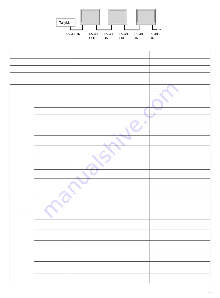
SWIT Electronics BM-U Series User Manual Download Page 17

Cascade:

17

6.  Assist— Setting for Vector scope and Histogram patterns.

Menu Item

False Color
Blue Only

Focus Assist

Zebra
Color Checker

Menu Description

Turn false color display on or off
Turn blue only on or off
Turn on or off focus assist and adjust the 

color of the focus assist
Turn zebra on or off
Turn color checker on or off

Value

OFF, ON
OFF, ON

OFF, Blue, Red

OFF, ON
OFF, ON

Waveform
WFM Type

WFM Position

WFM Blending

WFM Color

WFM Single Line*1

WFM Line Count

Vector

Vector Position

Vector Blending
Vector Color
Histogram
Histogram
Blending

Marker
Marker Select
Horizontal*2
Vertical
Safety area
Fit Marker
Center Marker
Marker Color

Marker Outside

Marker

Vector 

Waveform 

Histogram 
setting

Turn waveform on or off
Set the WFM Type

Set the WFM position
Set the blending of the background color of 

the waveform

Set the color of the waveform displayed on the 

waveform chart
Switch on single line waveform
Set a line for the single line waveform
Turn vector on or off

Adjust the position of the vector on the screen

Vector scope transparency selection
Set vector colors
Turn histogram on or off
Set the transparency of histogram 

background color

Turn marker on or off

Set the scale of the market line

Set the X coordinate value of the marker
Set the Y coordinate value of the marker
Set safety area percentage
Set safety area to fit marker ratio or not
Switch on the center cross marker
Select a color for marker

Marker outside color setting

OFF, ON
Y, Cb, Cr, R,G,B,RGB
Bottom Left, Bottom Right, 

Top Left, Top Right

OFF, High, Low

White, Green, Color

OFF, ON
1-2160

OFF, ON
Bottom Left, Bottom Right, 

Top Left, Top Right
OFF, Low, High
White, Green, Color

OFF, ON

OFF, Low, High

OFF, ON
16:9,15:9,14:9,13:9,4:3,2.35:1,

2:1,1.85:1,Custom

50%~99%
50%~99%
80%~99%
OFF, ON
OFF, ON
White, Red, Green, Blue, 

Black, Gray
OFF, Black, Gray

Summary of Contents for BM-U Series

Page 1: ...BM U 4K High De nition Monitor Model BM U175 245 275HDR User Manual Please read this user manual throughout before using Ver A SWIT ELECTRONICS CO LTD 01...

Page 2: ...LCD dot defects are not over three Any damage caused by using third party power adaptors Anydamageorbreakdowncausedbyuse maintenanceorstoragenotaccordingtotheusermanual The product is disassembled by...

Page 3: ...isconnect the power cable under the following situations A If you do not operate this monitor for a period of time B If the power cable or power adaptor is damaged C If the monitor housing is broken T...

Page 4: ...ne selection mode Vector scope R G B Y histogram bi color focus assist 3DLUT 17 x 17 x 17 accurate color correction Dynamic UMD and TALLY TSL3 1 4 0 display Composition ratio auxiliary line 4 3 13 9 1...

Page 5: ...INFO to exit the menu with one click 5 F1 F5 function keys Customize shortcut function keys Users can set the shortcut keys to di erent functions according to their own requirements 6 Brightness Cont...

Page 6: ...d into 4 frames and 4 channels of SDI signals can be displayed simultaneously When Four screen is opened some menu functions are turned o or displayed in grey 7 Menu Enter When no Menu is displayed pr...

Page 7: ...gh speed RJ45 Ethernet port for web server IP external control 5 HDMI 2 0 IN Will not display HDCP protected content 6 RS485 TSL UMD control port 7 GPI GPI control port 8 Fan 9 VESA bracket mounting a...

Page 8: ...MI embedded audio or analog audio The audio meter display channels on screen positions markers and background colors are adjustable User can set function keys F1 F5 or GPI pins as Audio Bar to turn on...

Page 9: ...tandard of SDI 1 2 3 4 channel is displayed in standard 2 Channel Displays the currently selected channel 3 Color Temp Displays the currently set color temperature mode 4 Scan mode Displays the curren...

Page 10: ...elected item and its parameters will be highlighted in yellow 4 Revolve Menu Enter to change the selected item s parameter press Menu Enter to apply and save the settings 5 Revolve Menu Enter to selec...

Page 11: ...Blue Gain Red Bias Green Bias Blue Bias Reset Import Reset Exit False Color Blue Only Focus Assist Zebra ColorChecker Waveform Vector Histogram Marker Exit Lissajous Lissajous Position Audio Bar Audi...

Page 12: ...color matrix Adjust Red Gain Adjust Green Gain Adjust Blue Gain Adjust Red Bias Adjust Green Bias Adjust Blue Bias Reset the gain and bias values of the settings Value 0 1023 4 1019 64 940 64 1023 Au...

Page 13: ...00 100 100 100 100 100 100 100 100 100 100 100 None 3DLut cube User Log cube NO 3DLut cube 1 Color gamut Set the gamut to match the input audio When Four screen is selected the color gamut value of th...

Page 14: ...F Odd Frame Even Frame 1 Scanning Panel Fit Turn on this feature to adapt the audio to the entire screen Native only displays the original mode in the speci ed mode 2 Zoom mode Shown below the image i...

Page 15: ...PI 1Pin GPI 2Pin GPI 3Pin GPI 4Pin GPI 5Pin GPI 6Pin Tally Setting Tally Position F1 F2 F3 F4 F5 UMD 2 UMD Color UMD Position UMD Size UMD Blending Display Type RS485 Address Baud Rate Source ID Value...

Page 16: ...ntrol and set the function of GPI 1 6 buttons The GPI control allows you to control both the Tally light and the on screen TALLY light on at the same time 2 UMD Select the display type as UMD which ca...

Page 17: ...the waveform Set the color of the waveform displayed on the waveform chart Switch on single line waveform Set a line for the single line waveform Turn vector on or o Adjust the position of the vector...

Page 18: ...ous on the screen Turn on or o audio bar Select the channel shown in the audio table when opening Four screen Set the display position of the audio bar Set the transparency of the audio table image ba...

Page 19: ...11 3 Start Calibration Steps 1 Put the monitor into a dark room Switch on the monitor 2 Connect the calibration instrument compatible with x rite and JETI color measuring instruments and monitor via U...

Page 20: ...rated in factory And may need to be re calibrated after a period of time Before re calibrated the measure function can check the current color to compare with the last time calibrated color to decide...

Page 21: ...be in the no signal state and turn on green mode Set up the monitor IP address to achieve remote web control Set OSD display time Set the brightness of the key lamp Select Chinese or English language...

Page 22: ...ormats the monitor is low latency itself whether low latency mode is on or o For interlace I or progressive segmented Frame psd formats turn on Low Latency Mode will get lower latency SDI Format 4096...

Page 23: ...r Menu System IP Net Mask Gateway Port to set the monitor address Set the computer Ethernet IP addresses at the same LAN environment as the Monitor Launch any of a web browser on the computer and ente...

Page 24: ...atest software package into the U disk root direction 2 Open the monitor and plug U disk into USB into port 3 Follow the step Menu System the monitor will update automatically 4 When update nishes pre...

Page 25: ...22 00 412 00 422 99 392 30 110 00 110 00 15 01 65 15 100 00 100 00 BM U245 145 00 30 60 120 00 120 00 15 00 75 55 41 20 91 13 382 00 472 00 652 30 433 10 463 79 75 55 15 00 120 00 120 00 100 00 100 00...

Page 26: ...5 66mm 3840 2160 1 07G 16 9 1000 1400 1 Horizontal Vertical 178 178 BNC 2 BNC 2 HDMI 1 RS 485 2 USB 1 ETHERNRT BNC 2 BNC 2 RS 485 1 12G 6G 3G HD SD SDI 2 3G HD SD SDI 2 HDMI input GPI 1 UMD 1 12G 6G 3...

Page 27: ...3 98 1280 720P24 1280 720P25 1280 720P29 97 1280 720P30 1280 720P50 1280 720P59 94 1280 720P60 1920 1080I50 1920 1080I59 94 1920 1080I60 1920 1080PSF23 98 1920 1080PSF24 1920 1080P23 98 1920 1080P24 1...

Page 28: ...2160P24 3840 2160p25 3840 2160P29 97 3840 2160P30 3840 2160P47 94 3840 2160P48 3840 2160P50 3840 2160P59 94 3840 2160P60 4096 2160P23 98 4096 2160P24 4096 2160P25 4096 2160P29 97 4096 2160P30 4096 216...

Page 29: ...e provided power supply reconnect the power Bad contact of BNC or HDMI cable Video signal has Interference Improper adjustment of the color parameters Distortion of the image Set to Blue only Turn on...

Page 30: ...g 210038 P R China Tel 86 25 85805753 Email contact swit cc SWIT Electronics Europe GmbH Add Hochstr 17 47228 Duisburg Germany Tel 49 0 20659799339 Email info swit europe com SWIT Electronics America...

Reviews: