80
UK
MV-1400-10-2019 . © All rights reserved Swim & Fun Scandinavia ApS
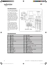
10.1 Wiring diagram
The electrical wiring diagram
is only for general reference.
The swimming pool heat
pump must be connected to
the ground wire, although
heat exchanger unit is elec-
trically isolated from the rest
of the unit. The unit must still
be earthed in order to protect
against short circuits inside
the unit. Bonding is also re-
quired.
A power switch should be
located within sight and be
easily accessible from the
heat pump. This is common
practice on commercial and
residential heat pumps. It al-
lows you to turn off the power
to the unit while it is in oper-
ation.
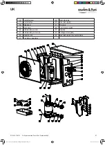
10.2 Exploded view
No.
Part name
No. Part name
1
Top cover
24
Fan motor capacitor
2
Back grill
25
Electric box
3
Side panel
26
Wiring clip
4
Evaporator
27
5 bit terminal
5
Fan motor bracket
28
Electric box cover
6
Fan motor
29
Water flow switch
7
Fan blade
30
Titanium heat exchanger
8
Fan panel
31
Clip
9
Front grill
32
Water inlet temp. sensor T1-TH6
10
Base tray
33
Drainage plug
11
Isolation panel
34
White rubber ring
12
Compressor
35
Rubber ring on water connection
13
Wiring connector
36
Water connection set
14
Pressure gauge
37
White rubber ring
15
Controller
38
High pressure switch
MV-1400-10-2019-ECO-Heat-Pump-Manual-BOG.indb 80
MV-1400-10-2019-ECO-Heat-Pump-Manual-BOG.indb 80
17-12-2019 15:25:09
17-12-2019 15:25:09


