9
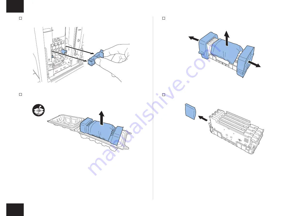
4) Remove Blade Cleaner.
5) Take out included Printhead from the package.
F-1-15
F-1-16
6) Remove the PCB cover and the cushioning materials.
7) Remove the 4 caps.
F-1-17
F-1-18
Page 1: ...ENGLISH ENGLISH COLOR LABEL PRINTER SCL 4000D Installation Procedure PRINTED IN JAPAN PUB No 4Y8 8014 020...
Page 2: ...he outlet 100V 240V AC 10 15 exclusively 2 There must be an easily accessible outlet near Printer Checking the Installation Environment 1 The installation environment must be as described below Avoid...
Page 3: ...curs when the machine is moved from a cold place to a warm place Leave the unpacked machine as it is for at least two hours before installing it Dew condensation When a metallic object is brought from...
Page 4: ...wer Cord x 1 for 230V series 5 Spare papers 4 5 inch x 20 CAUTION Several types of Power Cords come with Printer Use appropriate Power Cord for the power supply used at the installation site NOTE When...
Page 5: ...edure described below remove all pieces of fixing tape and cushioning materials before installing Printer Keep the removed cushioning materials for future transportation for relocation or repair of Pr...
Page 6: ...sons are required to lift it Do not hold the front side of Printer F 1 6 F 1 7 5 Place Printer on a horizontal table and then remove all pieces of fixing tape and cushioning materials visible on the e...
Page 7: ...ng tape inside Printer NOTE Keep the removed cushioning materials because they may be used for future transportation for relocation or repair of Printer 10 Turn Pinch Roller Release Lever and then rem...
Page 8: ...Printhead Unit 1 Remove 2 screws to remove Maintenance Cover from Upper Unit x2 2 Close Upper Unit F 1 11 F 1 12 3 Remove Print Module Cover and then open Upper Printhead Release Lever and Lower Print...
Page 9: ...9 9 4 Remove Blade Cleaner 5 Take out included Printhead from the package F 1 15 F 1 16 6 Remove the PCB cover and the cushioning materials 7 Remove the 4 caps F 1 17 F 1 18...
Page 10: ...rail guide and then insert it into Printer until it stops NOTE Skewering Shaft must be on Printhead Guide Rails CAUTION If Printhead is insufficiently inserted Lower Printhead Release Lever cannot be...
Page 11: ...11 11 10 Mount Blade Cleaner in Printer F 1 23 11 Close Lower Printhead Release Lever and Upper Printhead Release Lever F 1 24 F 1 25...
Page 12: ...nt Module are visible NOTE If any one of numbers 1 2 and 3 is invisible Printhead Release Lever 1 2 has not been closed or Blade Cleaner 3 has not been mounted Review work procedure F 1 26 13 Attach P...
Page 13: ...13 13 14 Push down Upper Unit Open Lever and then open Upper Unit 15 Mount Maintenance Cover on Upper Unit x2 F 1 29 F 1 30 16 Close Upper Unit and then close Roll Cover F 1 31...
Page 14: ...nk Tank Door 2 Open Ink Tank Lever for each color while pushing it downward F 1 32 F 1 33 3 Take out included Ink Tanks from the packages and then remove the cushioning materials NOTE The amount of st...
Page 15: ...t will go and then close Ink Tank Lever CAUTION Ink Tank cannot be loaded properly if it is inserted in a wrong Ink Tank Slot 5 Close Ink Tank Lever F 1 35 F 1 36 6 After checking that all Ink Tanks h...
Page 16: ...veral types of Power Cords come with Printer Use appropriate Power Cord for the power supply used at the installation site CAUTION Never use a wrong Power Cord 2 Connect Power Cord to the outlet 3 Tur...
Page 17: ...reference to the included Start Guide Load printing paper that is usually used in Printer 2 Print any image that is usually used with reference to User Guide included in Printer Software CD ROM and t...