8
BULB REPLACEMENT
Unplug the stereo microscope from the electrical outlet and
remove specimens from the stage before you attempt to replace
an LED.
To prolong the life of the LED, you should always turn off the unit
when not in use.
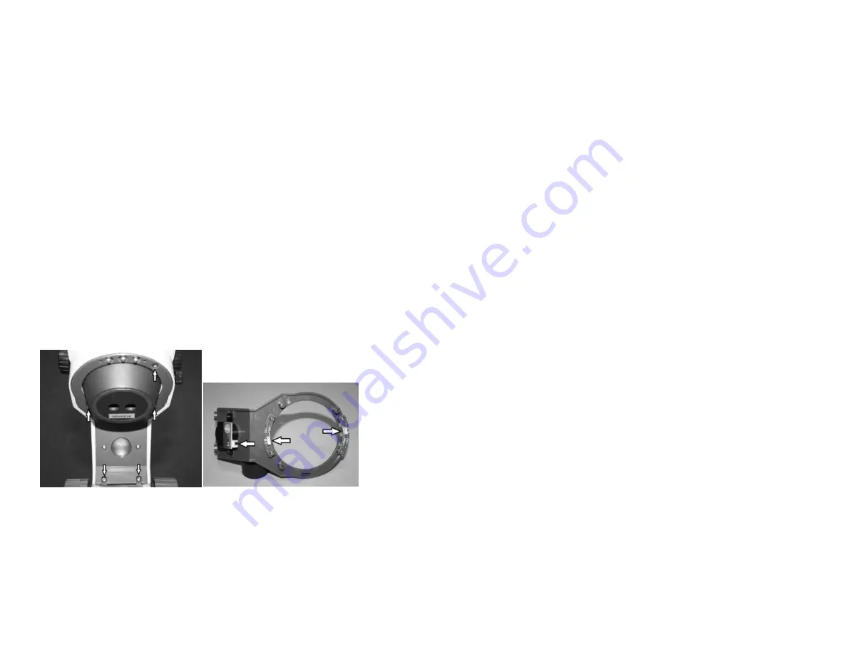
The extra long life LED incidental (top) illuminator bulbs (Swift
MA14780 & MA14781) can be replaced by removing the five retaining
screws holding on the Illumination plate (See Fig 1.). This will
require the use of a short handle screw driver. They can then be
unclipped and replaced (See Fig 2.).
The transmitted (bottom) illumination bulb is Swift MA14782 3.5V
150mA LED Bulb. The bottom bulb may be replaced by carefully
laying your stereoscope on its side and using a Phillips screw driver
remove the four screws securing the rubber feet and base plate to
illuminator base. Remove four 3mm Phillips head screws securing
lamp housing to lamp bracket; then remove lamp housing. Carefully
unplug LED lamp connector. Replace LED lamp assembly and then,
reverse the above process.
Fig 1.
Fig 2.
5
COMPONENTS OF THE STEREO MICROSCOPE
BOTTOM ILLUMINATOR – This is the light source mounted in the
base to provide trans-illumination.
DIOPTER ADJUSTMENT – Located on the left eyepiece tube of the
SM100 Series. This adjustment is used to fine focus the optics to
compensate for visual differences between the user’s eyes.
EYEPIECE – The upper optical element that further magnifies the
primary image of the specimen and brings the light rays in focus at
the eyepoint.
EYEPIECE TUBE – This is the part of the head that holds the
eyepieces in place. Set screws in the eyepiece tubes can be used to
lock the eyepieces in place.
STAGE CLIP – Used to hold specimen in place.
FOCUSING CONTROL KNOB – The focusing control knobs located on
either side of the stand are used to raise or lower the head to bring
the specimen into focus. The control knobs incorporate a slip
clutch system which prevents the head from traveling past both
ends of the focusing range. When the focusing limit is reached, the
clutch system begins to slip to prevent gear damage.
HEAD – The 360˚ rotatable component that contains all of the
optical elements of the stereo microscope including the eyepieces,
refracting mirrors and objective lenses. The head of the SM100
series is designed to allow users to adjust the interpupillary
distance of the eyepieces for proper viewing.
ILLUMINATOR DIMMER CONTROL – The intensity of the top
(incident light) LEDs or bottom (trans-illumination) LED can be
adjusted to the preferred brightness (0 through 10) by using the
dimmer control located on the side of the base.
ILLUMINATOR ON/OFF SWITCHES – A tri-illumination system is
incorporated into the stand. The illumination system is controlled
by top (incident light) and bottom (trans-illumination) on/off
switches located at the base of the stand. The incident illuminator
is used for opaque specimens, while the trans-illuminator
effectively illuminates the internal structure of transparent
Summary of Contents for SM100 Series
Page 2: ......


