background image

Swift

User Manual

10. Additional Instructions
10.1 Remote controller settings

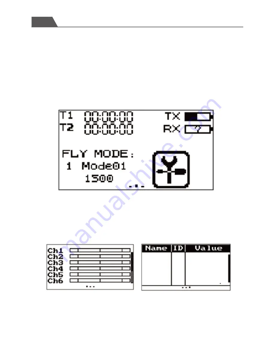
Boot screen(Main interface)

Display actuator 

-17-

Caution: Power off the throttle to avoid damage and personnel injuries before checking  

the actuator. 

Slide the acutators up and/or down to adjust, long press to check the position or status.

T1 \T2

Timer and setting menu

FLY MODE: Current flight mode and setting menu

TX/RX: Status and voltage settings menu

Attention: We strongly recommend that the default settings 

of remote controller are not changed. These setting changes 

are intended for senior pilots. 

Summary of Contents for SWIFT 2

Page 1: ...SWIFT 2 Racing drone User Manual www swellpro com Do not blink because it s fast...

Page 2: ...3 Specifications 6 4 Important Before you fly 8 5 Charging the battery 8 6 Preparing the drone 9 7 Ready for flight 11 8 Operating Instructions 13 9 At the end of the flight 16 10 Additional Instructi...

Page 3: ...nces power and reduces maintenance A professional compact and aggressive ready to fly and yet elegant racing drone Do not blink because it s fast The Drone User friendly Radio Controller providing you...

Page 4: ...know your Aircraft 1 Camera 2 Propeller CW 3 Propeller CCW 4 Clockwise motor 5 Counterclockwise motor 6 Li Po Battery 7 Power connector 8 Mushroom antenna 9 Reciever antennas 10 Indicator lights on th...

Page 5: ...OSD ON OSD OFF Lock Motor Unlock Motor Left Joystick Right Joystick Power Power Alarm Battery cover PS 2 No function USB Alarm Touch screen Please Note The factory default setting of the remote contro...

Page 6: ...Flight mode in this mode the Swift s operation is relatively stable it can not roll it is recommended for beginners INTERMEDIATE flight mode in this mode the Swift s operation is with partial stabiliz...

Page 7: ...mensions L x W x H 183 x 216 x 85mm Weight 378g Battery excluded Brushless Motor 2205 2300KV Brushless ESC 25A Battery 3S 2600 mAh LiPo Weight 214g Transmitter 5 8G 40CH Digital Channel Selector Fligh...

Page 8: ...ance 1 0 KM Receiver Sensitivity 1 PER 105dbm Working Current 120 mA Battery Operating Voltage 7 4V 11 1V Channels 10 Camera Horizontal Resolution 800TVL Video Options PAL NTSC Power input 5V FOV 120...

Page 9: ...Do not fly close to high voltage power lines cellphone towers or radio towers as these may disrupt your control signal NEVER fly over crowds concerts or sports stadiums Connect the power cable to the...

Page 10: ...according to the direction of orange arrow Tighten the propellers manually making sure the propellers are installed in proper way and securely fastened Install prop by hand tighten by with the include...

Page 11: ...e battery on top of the anti slip mat Move the battery forward backwards as required to establish perfect balance then firmly secure the battery with the velcro strap Please read Centre of Gravity adj...

Page 12: ...acing you 2 Please ensure that video receiving equipment is setup and ready for use displaying an image and OSD information 3 When all is setup prepare for take off and flight Please consider the poin...

Page 13: ...Swift User Manual 7 2 Motor unlock 12 Place the throttle joystick at the lowest position Move switch SWA to it s lowest position to unlock the motors...

Page 14: ...n instructions the direction of the head up down The rear toward operator Remote Controller Instructions Throttle forward backward Indicator light instruction Pitch left right Indicator light instruct...

Page 15: ...roll backward 14 Make sure fly in the Intermediate Advanced flight mode the direction of the head Remote Controller Instructions Aircraft Reaction Attention Always select large open spaces with soft g...

Page 16: ...nding on the local environment Avoid flying over people animals or high voltage lines Obstacle flying Attention Always select large open spaces with soft ground for flying Rolls and flips are best sui...

Page 17: ...the powering off the motors 2 If the aircraft goes down in some areas that are not easy to find you can hold the alarm button resulting in the buzzer sounding on the drone to assist you in finding it...

Page 18: ...njuries before checking the actuator Slide the acutators up and or down to adjust long press to check the position or status T1 T2 Timer and setting menu FLY MODE Current flight mode and setting menu...

Page 19: ...the list to enter the settings menu Click the return icon to return to the previous menu Main interface display Making operation more easier and simple Setup To change between normal and reverse touc...

Page 20: ...ol The left box is the low end point the right box is the high end point marked below as low end point being blue and red being the high end point 1 Touch the low or high end points box 2 Touch the de...

Page 21: ...an select between the two output modes of the receiver PWM mode and PPM mode Select the applicable output mode according to requirements The black dot icon indicates the currently selected mode Below...

Page 22: ...t channel E short press the button to choose channel E1 Now the system will circularly indicate frequency E channel 1 without any operation 2 In order to get E5 please short press the button 4 times c...

Page 23: ...system will show the current power level the number blinks slowly 2 To enable the change of power level short press the button once to select the desired power level from the following options 1 25mW...

Page 24: ...their top locations in opposite direction to setting PID Right stick to selects the item Use the left stick to adjust the value pull right to increase the value and pull left to decrease the value Th...

Page 25: ...Charging is complete when all the indicator lights stay on solid 1 Please make sure the correct battery type is used always power on the changer before connecting a battery or damage to the hanger and...

Page 26: ...different types of battery packs Do not allow children under 15 years to use the charger to avoid accidents Do not charge in overheated or overcooled places avoid placing the charger in direct sunligh...

Page 27: ...1 2 3 Loosen the screws and release the frame on the top of the camera Fix the G mount on the top with screws provided Please ensure it is in the right direction Fasten the camera with the strap loose...

Page 28: ...ount on the top with screws in the right direction Fasten the camera with the strap loosen the side screws adjust the camera angle to your own preferred angle and then tighten the screw Please Note G...

Page 29: ...175 Email info swellpro com Address D15 shengang Flower Center Shohe West Road ShenZhen China 51800 This manual is subject to renewal without prior notice Please refer to the Swellpro official website...

Reviews: